Jump to content

Inyri

Members
  • Posts

    547
  • Joined

  • Last visited

Everything posted by Inyri

  1. This video tutorial shows rudimentary UV mapping by using gmax. This tutorial was made on the spot, and I had no idea how to properly use gmax, so it's a very good demonstration on how to approach it as a beginner . This tutorial should only be used to get started UV mapping for beginners. https://youtu.be/WdX9h6A75ms
  2. This tutorial will take you from reference to in-game on how to make a lightsaber hilt. It covers reference, modeling, uv mapping, exporting, and all the steps it takes to put the PK3 together and get the model working in-game. Meant to be a replacement for the popular but outdated tutorial by Virtue. Tools you'll need GmaxMD3 ImporterMD3 ExporterImage editing software, such as GIMPMD3ViewNotepadPakscapeThe first thing you need to do when making a hilt is to have an idea of what it is you want to make. Reference images are a dream, so if you have an idea for a hilt try drawing it on a piece of paper, using your image editing software to sketch out a rough design, or use a third-party site like saberBuilder. I'll use the last option for this tutorial, since it's a quick easy option for those of us who may not be the best artists when it comes to drawing. After a few minutes I came up with a simple lightsaber design that we can use to base our hilt on. Remember, you can make your hilt as simple or complex as you like, but remember to make sure you only make your design up to the level of skill you posess. The more you model the better you'll get, but there's no sense in trying to make a model you're simply not skilled enough to make, otherwise you'll get frustrated! This should be a simple hilt for starters to attempt, so if you're interested in following along make sure to download the image. The next thing we need to do is open GMAX and get ourselves ready to model. I recommend doing most of your work from one of the FRONT viewport. Click on it once, then click the Views menu at the top, then choose Viewport Background (or skip all that by hitting ALT+ B ). Under theBackground header click Files and navigate to where you saved your reference file. Under theAspect Ratio header make sure you click Match Bitmap, which will allow the Lock Zoom/Panoption to be selected. Check that box so our background won't move with us as we zoom or pan. Your screen should look something like the following: Now we can start building our hilt from this image. Almost all modders in the Jedi Academymodeling community strongly recommend eight (8) sided cylinders for lightsaber hilts and other cylinder-based models. This allows your model to still look round in-game, but will reduce the amount of stress the model puts on the engine by keeping the hilt efficient. Make sure when you use the cylinder tool to set the sides to eight and the height segments to one. Return to the front viewport and let's make a cylinder by clicking on the Create tab . To get a better look at what you're doing you may want to maximize your viewport. Once you're ready to start click on the Cylinder button and make a cylinder roughly the width of the hilt in your drawing or reference. We will have to rotate it when we're done so it matches the shape, size, and orientation of our image, but you should see something like this when you finish: Now we have our basic shape, but we need to make it look like our reference. I am going to extrude those small rings so they stick out a little, even though that's not exactly how they look in our reference. This is personal preference, but it will give our model some depth instead of just being a flat cylinder. I have counted that I will need five additional edge loops -- one for each side of those rings -- so I will just go back into the Modify tab and change the height segments to six (6). This isn't exactly what we want, so I'm going to right click on the model and choose Convert to: and then select Convert to Editable Poly. You can also choose Convert to Editabe Mesh, but I am more used to working with polies. NOTE: Once you do this you will not be able to change any more parameters for your cylinder because it will no longer be considered a cylinder anymore, but instead an editable mesh or poly (depending on what you chose). Now that I've converted it I can use the vertex tool to move those edges where they belong. Now we're going to take these polygons we just created and extrude them. Select just the polygons in the ring, then right click and select Extrude. Click and drag until they are extruded to your liking. If the polygons are extruding strangely you may need to click on the Modify tab and scroll down until you see Extrusion type. Make sure Local Normal is selected. You can see before an after image below. Now we'll work on the emitter -- the bit the blade will come out of. To make it look like the emitter in our reference we'll have to move some vertices around. Just move them to the left until they line up with the outline of our reference. Once you've done this it will look like the image below. Finally! It's looking good now. One last detail we should add is to hollow out this part of the emitter. To do this you may want to go into perspective mode by hitting the P key. There are a variety of ways you can do this, but not being very familiar with GMAX myself I decided to do some beveling. By clicking the Bevel button and choosing a small number for the Extrusion value and a larger, negative number for the Outline value I was able to somewhat mimic what the Inset polygon tool does in 3DS Max. I then extruded the inner portion backwards (click and drag, or use a negative value for your Extrusion value. You can then either leave the lip portion as it is or you can move those vertices you beveled back in line with the outside ones. So what you'll have now is: Now it's time to UV map. Not my favorite part of modeling either, especially in GMAX which has some pretty poor tools. But we'll give it a try together. Luckily it does have some tools that will make unwrapping our cylindrical hilt about 1000x easier, so in your modifier drop down menu select UWV Map. In the roll-out click Cylindrical (and check Cap to make things easier for yourself), then scroll down and select the Fit button. This probably won't appear to do anything, which is actually good. It means the modifier was applied perfectly without us having to mess with it any more. Now in your modifier list select Unwrap UVW. Click edit and look at your map. Looks a little odd, but it's definitely workable! This will take some by-hand tweaking, though, so get ready to learn a thing or two about mapping your hilt the hard way (also known as "the right way"). The first thing we're going to do for ourselves is apply a checkered pattern to our hilt. This will help us figure out which parts of the texture will stretch. The idea is, when you're done with your map, all the squares should be squares (as opposed to rectangles, triangles, blobs, minesweeper mines, etc). Hit M to enter the material editor, then apply the checkered texture of your choosing. To create a texture click New, then choose Standard. You'll now see a bunch of stuff, but click where it says Maps to expand that roll-out, then click the nonebutton next to Diffuse Color and select your checker pattern by clicking on Bitmap and then navigating to the texture. You can then drag the new texture onto your model (make sure to click the little button with the box covered in blue and white checks to make sure you can see it in the viewport!). Now for the hard part. You need to separate your UV map. Remember, you ideally do not want any parts overlapping, and you can scale, rotate, and move any pieces you want. If the checkered background is bothering you, you can also turn it off by clicking the box with the blue and white checks in the Edit menu in the Unwrap UVW roll-out. The first thing you want to do is select those big circles and move them out of the way. Just move them off to the side for now so we can work on the rest of the map. As you can see if you zoom out a little on our map, we have some strange parts sticking out to the right and left. Don't worry about these parts; they are the edges of our rings and they are on a different plane, so we will have to fix them later anyway. I am going to carefully select them and detach them from the main map (right click, select Detach Edge Verts) and move them out of the way as well. When cleaning up your UV map make sure you don't have any overlapping sections, and that all the checks on your model at the very least look the same. If they are all slightly stretched make sure they are equally stretched. That way when you finish you can universally scale them all together to get them square. What I noticed when I was working with this UV map that the curved part was actually upside down, since it is the inside of the emitter. Simple select the bottom vertices and drag them up, then you can make sure the polygons below them are wide enough (these are the lip on the emitter). The flat portion on the very inside you may want to select and use the planar mapping feature on. It should be set to Averaged Normals by default, so you can choose that face and click the Planar Map button. You can also use this feature on the portions of the rings that we moved off to the side, but make sure to select the Z plane instead of Averaged Normals. You can then move these out of the way again. Once you are satisfied with your map, scale it so it fits in the black box. Mine looks like this: Okay, we're done UV mapping so now we need to texture our hilt. You'll need to export your skinmap and we'll have to do this the hard way since it's GMAX. With your UV map open, hit thePrint Screen key on your keyboard (sometimes PrtSc or similar) and past this into your photo editing software. You will now only want the bits inside the black box, so crop it to those dimensions and then resize the whole image to 512 x 512, which are the dimensions we need to use for the game. Now make a folder on your hard drive (prefereably in the root directory of your hard drive, to keep the pathway short -- this will help you avoid errors in ModView and MD3View) an call is base. Then inside this folder make a folder called models. Inside that folder make a folder called weapons2. Inside that folder make a folder with the name of your hilt (I will use sabertut). The following directory structure for me, for instance, is C:\base\models\weapons2\sabertut. Put your UV map here (you can call it anything you want). Now we're going to paint our texture over this map and we'll use the edges as a guideline. Feel free to paint a little outside of the lines to make sure you don't accidentally miss some spots right around the edges. I'm just going to make this simple and make the whole thing chrome and I'll only use three colors -- white, black, and silver. The silver I'm going to fill the background with, then I'll use the black and white to paint on the hilights. Even if you want your hilt to be chrome you don't have to make it look like chrome. Chrome is a result of light on the metal, so painting on chrome will just make it look fake. Let your shader do the work for you here, but we'll need a little depth, so we'll just do some hilights and shadows by painting big lines on the texture and blurring them. See how I did it below: Now we need to apply this texture to our hilt to see how it looks, otherwise we're just shooting in the dark. You can make a new texture just like we did for the checkered texture and apply it to your hilt to see roughly how the model will look with your custom texture. You can also keep working on it and see it change as you update the texture. I'm going to make a few more alterations then we'll see how it looks! Alright, our hilt is now modeled and textured. Now comes the important part: getting it in-game. We need to import an existing game hilt so we can figure out how big to make our hilt. We also need to get the tags from an original hilt (otherwise we would have to make our own). Let's use PakScape to open up one of Jedi Academy's assets PK3's and grab a hilt to use as a reference. I am going to pull the folder called "saber" out of assets1.pk3, then I will use the MD3 import script to import the MD3 into our scene. Make sure when you're using the script you choose Load All under the Tagsheading. Hey, I don't see my saber! That's because the saber we imported is so small it's inside our model! Click on your mesh and hit ALT+X to go into xray mode and you should see it. We'll need to scale our model down and rotate it so it is the same size and orientation as the model we just imported. It's okay if our hilt isn't quite as long as the original, so make sure when you're scaling your hilt you base it on the width of the original hilt, not the length, otherwise your character will look like he or she is holding a giant, thick flashlight instead of a lightsaber. Now I've got it scaled, so our scene should look like this: Just to be safe, hit Reset XForm in the Utilities tab. Jedi Academy is not as picky about model transforms as some games are, but it's still good to be safe. Now we can delete the original hilt (just the hilt, not the tags!). You should see that a little triangle is left over. This is our tag and the game needs it to know where to put the saber blade (otherwise you'll get the dreaded crotch-saber). There should be one tag called tag_parent, which you can ignore, and another called tag_blade1 -- that's fine, so leave the name as it is. You maybe need to move it up or down, depending on the size and orientation of your model, so in our case we'll either need to move the tag down, or we'll need to move the hilt up. I am going to move the hilt up slightly, just to make sure we get good hand placement. Now we'll export. This is the easy part, assuming you've done everything right up to this point. Go toFile, then Export. Select Quake III MD3 as your filetype if it's not preselected and name your model saber_w.md3 and save it to the folder we made earlier for our model (C:\base\models\weapons\sabertut for me). Make sure when you export you choose the following options: Done with GMAX. Phew! Navigate to the folder you saved the MD3 to and open it with MD3View (if this is the first time you've used it you may have to tell the file to open with MD3View. When you open the hilt you may sometimes get spewed a bunch of long funny-looking errors and you will find your model is displayed white, without its texture. Sometimes this will happen and sometimes it won't, but I find it easiest to pretend like it always does and always take the following corrective steps. Jedi Academy does not automatically know what texture you want applied to your model so we need to tell it. With a basic text editor (like notepad, which comes with Windows) we'll quickly tell it where to look for our texture. The format the game will look for is meshname,pathway. Some tutorials will tell you that you must name your mesh a certain thing, such as saber_w. In all honesty I didn't bother changing the name of my mesh, so it's still named Cylinder01. That's fine; Jedi Academy doesn't care. I just need to make sure my text file reads asCylinder01,models/weapons2/sabertut/sabertut.tga. You'll want to note two things here. First, you always start the path from the top folder under base. In this case it's models. Secondly, we always use .tga as our filetype, even if your texture isn't a targa. Mine is a jpg, for instance, but the gamealways looks for a .tga ending in these files and it will be angry if it doesn't find it. When you're done making your text file save it as saber_w.skin (make sure if you're using notepad you set the filetype to All files otherwise instead of saber_w.skin you'll get saber_w.skin.txt, which won't work). Save this in the same folder with your model, then back in MD3View go to the Filemenu and select Import skin and choose your .skin file that you just made. Now select Export MD3 from the file menu and overwrite the MD3 you made with gmax. Now select Export as GLM (Ghoul 2) *without* 90-degree skewing ( added for JKA ) and save this new file in the same directory with the same name. You should have three important files now if you've been following along: saber_w.md3, saber_w.glm, and the texture we made earlier (I named it sabertut.jpg). You will not need the .skin file we just made anymore, so you can forget about it. It has done its job. We're not quite ready to put this in-game yet because we need to make another file to help Jedi Academy know what to do with our hilt. We need to make a saber file. Open assets1.pk3 back up and look for single_1.sab in ext_data/saber. Pull this out and save it to the folder you made for your hilt and rename it sabertut.sab. This file will probably be labeled as read-only, so right click on its icon and select properties, then uncheck read-only. Now open the file with a text editor (such as notepad). The top line should say single_1 -- this is what the game knows the hilt as. We need to change this so that our saber doesn't overwrite one of the game's default sabers. I will change it to sabertut. The next line with text should say name. Change the name from @MENUS_SINGLE_HILT1 to whatever you would like your saber to be called in the game. I will name mine "Tutorial Saber". The last thing we need to do is change the model to ours. Your file should look like this: sabertut { name "Tutorial Saber" saberType SABER_SINGLE saberModel "models/weapons2/sabertut/saber_w.glm" soundOn "sound/weapons/saber/saberon.wav" soundLoop "sound/weapons/saber/saberhum4.wav" soundOff "sound/weapons/saber/saberoff.wav" saberLength 40 saberColor random } Now we're ready to finally put this in-game! Open up PakScape and we'll get everything packaged up and ready to go. You will need the following directory structure if you've been following along: Put your MD3, your GLM, and your texture into the sabertut folder. Put sabertut.sab into the sabers folder. Now save your PK3 to your base folder (/Star Wars Jedi Knight Jedi Academy/GameData/base or similar). You can give the PK3 any filename you want. Now let's try it out in-game! As you can see below, the hilt turned out okay! More advanced modders might be able to add shaders to make the hilt shine or have a chrome look, and you can see the hilt is probably just alittle bit too thick, but with the knowledge you've gained you could go back and tweak it until the model is just the way you want it. Congratulations, though. You just made your first hilt and got it in-game!
  3. Program used: 3DMax 7 http://www.youtube.com/watch?v=b6UfCittExQ
  4. This simple but comprehensive tutorial will teach you how to make a very basic sword model from generic shapes. It is ideal for learning to make weapons for video game modding. Tools you will need 3DS Max (or gmax)Image editing software, such as GIMPNOTE: This tutorial was written with 3DS Max in mind. Some parts may not be compatible with GMAX - I can't say for certain because I don't use it and don't know what functions it doesn't have. See the attached key below to find all important buttons/functions listed in this tutorial: This tutorial will cover all aspects of both modelling and skinning a very simple sword - a Roman gladius. This sword will need the following basic shapes: a plane (or box), two spheres, and a cylinder. That's right! You can make a sword out of just these basic shapes. I purposely picked a very simple design to begin with. It's never good to try and learn to do something by starting out with something complicated. The first thing we want to do is find a good reference picture. I've already done this for us by using a quick google search. Searching google is one of the easiest ways to find good reference pictures without having to do much work yourself. For self-concepts or less common models you may have to draw your own references. If this is the case you just want to make sure your reference is as straight as possible (you may even want to open the image with your image editing software and rotate it until it is as straight as you can get it). This will help in the modeling process. So here is our base reference image: As you can see, this image is only from the front. We will have to "guess" what it looks like from the side. It is okay to assume that the hilt portion is either perfectly round or slightly ovular - whether you want your grip to be round or an oval will be up to you - it really doesn't matter. I am guessing both the sphere on the bottom and the guard separating the hilt and blade are also round. This will be important later. The first thing we want to do is open up 3DS Max or GMAX and start out with a fresh scene. Pick a viewport - I usually use the front viewport - and hit ALT + B. This will bring up the viewport background window. What we want to do is add our base image as our viewport background. Find it, wherever you saved it on your hard drive, then under Aspect Ratio select Match Bitmap. Just to the right, make sure both Display Background and Lock Zoom/Pan are selected. Click OK. So now we should see our gladius image on the background of our viewport. If you find the grid distracting, as I usually do, you can turn it off by right clicking the viewport name and selecting Show Grid. This will toggle the grid off. There, now I can see my reference better! At this point I would zoom in to your selected viewport by hitting the Maximize Viewport Toggle button in the very bottom right. You will probably also want to zoom out by using your mouse scroller. So now what? We have our image, but how do we start? First of all, make sure yo'ure in the create tab. I use a plane method to make all my sword blades, so I don't have to worry about two layers of vertices, but you can just as easily use a box and skip the extrude step I will get to later. This tutorial will go over the plane method. Make a plane roughly the size of your blade. Don't worry if it's not perfect. Once you have made your plane, you may want to change the viewport rendering to Smooth + Hilights. Find this in the same place as Show Grid. Now hit escape to deselect the plane tool and select your plane. Hit ALT + X to go into x-ray mode and F4 to show your edges. If you see lots of edges, go into the modify tab and change your length/width segments to one. MODELER'S HINT! It's always easier to add edges than remove them! If in doubt, use less detail than you need. You can always add more later, but removing detail can be a pain! So now your viewport should look something like this: What we want to do now is right click on the plane, go down to Convert To and chose Editable Poly. This will bring up the Editable Poly Roll-out. Select the Edge Tool and select the two long edges. Right click and select Connect. You should now see an edge in roughly the middle of the blade. Using the Move tool, drag it up to where the blade first begins to narrow. At this point, your viewport should look like this: Now we want to select all three of the short edges and hit Connect. This should draw a line right down the middle. Now I will teach you a time-saving technique for use with symmetrical objects. Select the Vertex tool and delete all the vertices to the right of that center line. That will destroy the right half of your plane. Unselect the vertext tool and select your plane. Hit the Mirror button and make sure it it set to X. Then under Clone Selection choose Instance. This will copy the right half of your blade to the left half, so whatever you do to one side will be mirrored on the other. Handy, huh? Now select the left side again, and select the vertex tool. We will now use the Target Weld tool. Select the target weld button and click on the top left vertex. Now click on the top middle vertex, where the point of the sword is. Now our plane looks a little more like it's supposed to! You'll notice the shape isn't quite right, as the gladius narrows a bit at the top. No worries! With the vertex tool, select the top right vertex (not the point of the sword!) and with the move tool move it to the right until it matches the reference image. You may also have to move the bottom left vertex out as well. Now you should know enough about the basic tools to be able to do this, though! Move the outer vertices around until you're happy with the general shape. So now what do we do? All we have is a flat plane. Now comes the fun part. The first thing we want to do is combine the two halves of our sword to avoid headaches later on. Because the right side is an instance, we can't attach them directly. So what do we do? Delete it! Repeat the process of making the instance, but this time chose to copy it as a copy. Now you can choose Attach from your modify panel and click on the other side of the blade. To reduce the vertex count, use the vertext tool, select all vertices, and click Weld. With the default number it should weld all the middle vertices without welding any vertices you don't want to weld. Now that our blade is complete again, use the Polygon tool and select all the faces of your blade. There are only four, so it's not a big hassle. Just hit CTRL + A to select all. Now hit Extrude in your roll-out. Don't see a difference, do you? Now we'll need to go to a different viewport to see what we're doing. Hit Cancel and press the P button on your keyboard. This will send us to the Perspective viewport. Don't worry that your base image is gone - it's still on your other viewport. Zoom out so you can see your whole model and use the Viewport Rotate button to get a good angle on your blade so you can see both the front and side. With all faces still selected, once again hit Extrude. Now we can see what's happening! This will only be one side of your blade, so the default 10 should be okay. We can always increase it later if we need to. Click OK. So our sword now should look like this: Now we're going to use the Target Weld tool again to make the blade sharp - nobody wants to use a dull blade! Weld the vertices of the front to the back, leaving the middle vertices where they are - you have nothing to weld them to anyway! This is easiest to do in perspective mode. Remember, you can turn edges on here too by hitting F4. Here's another trick, to make sure your blade looks sharp. With the Polygon Tool select the faces of one side of the blade - right or left. Scroll down in the rollout until you see Smoothing Groups. Underneath this will be buttons numbered 1 to 32. 1 should be hilighted in yellow. Click it so it is grey, then click the 2 next to it so that the 2 is yellow. This will cause one side of your blade to have a different smoothing group than the other, making it have a hard edge. This will help your blade to look a bit harder. For smoothed blades you'll want to forgo this step. Now to make the back side of our blade we will once again employ the mirroring technique, but this time choose Y as your axis. You can mirror as a copy if you like and attach the front to the back if you're sure you aren't going to make any more changes. If you think you might alter your blade later, copy it as an instance again. You can skip the welding phase here also if you like. This will keep the blade from smoothing around the edges. For swords with higher vertex counts you will want to weld them and apply different smoothing groups to either side, but this sword has so few polies in the blade that it is unnecessary. So now our blade is done! Phew! Let's move on to the hilt. Hit F to go back to your front viewport. Use the Pan tool to get a good view of the hilt area and zoom in if you need to. We will make the hilt before we make the guard. From the Create tab select Cylinder. A section will pop up called Parameters with a bunch of options. Change the Height Segments to 1 and the Sides to 8. Anywhere from 8 to 12 sides should be sufficient for current gaming purposes (the game engine will smooth these faces and you will not see a difference even if you use additional edges). Using more sides than that is simply wasteful. Put your mouse cursor at roughly the middle of the hilt and click, dragging ds until the edge of the cylinder is close to the edge of the hilt in the picture. Drag the mouse a little bit and click again - this determines the height of the cylinder. Since you can't see how long you made it, we'll worry about changing it later. Hit escape to deselect the cylinder tool. Once again hit ALT + X to put this cylinder in x-ray mode. The cylinder isn't facing the right direction, so we'll need to rotate it. If you have 3DSMax you can use the Angle Snap Toggle to make sure you rotate it exactly 90 degrees. If you have GMAX you'll just have to be a little more careful, as I'm told it lacks this function. Click the Rotate tool and rotate the cylinder 90 degrees. That should look more like a hilt! Move the cylinder up or down and use the Scale tool to scale it only up and down (select just the green part and pull it up or down, depending on how you rotated your cylinder). Position the cylinder so it approximately covers the hilt. To compensate for our hilt guard and pommel section we will need to make it a little bit longer on both ends. I forgot to tell you to do this for the blade, so we'll fix that later. Your model should look something like this at this point: You can see our hilt isn't quite the right shape, as we did with the blade, change the cylinder to an editable poly. Using the vertex tool, select all of the bottom vertices and scale them (you can scale in all directions this time by clicking the center of the yellow portion and dragging) until the are about the width of the bottom of the hilt in the picture. Do the same with the top. Now we have this: Much better! Our hilt is done! Wasn't that easy? So now we have to do the pommel and the hilt guard. This'll be a little bit more complicated, but not too bad. For these we will use the sphere tool. The first thing we want to do is fix our blade. It isn't quite long enough right now, so we want to drag the bottom verts down so they're just overlapping the hilt guard in our picture. This will ensure our model doesn't have any holes. Overlapping objects isn't a bad thing. In fact it is often the easiest way to make sure your model doesn't have any gaping holes in it! Now select the Sphere tool from the Create tab. Change its parameters so the Segments are about 10 or 12. Twelve segments will be much easier to work with for our purposes. To get the sphere to match our reference, place the cursor near the middle of the very bottom of our blade, click, and drag. If it doesn't match up with the picture, use the move tool to reposition it. Remember to put it in x-ray mode! To make things easier for ourselves, let's rotate this sphere 90 degrees up so that it has a straight line across the middle, where our hilt guard and blade will meet. It's a good thing we picked 12 sides, because the mid line falls right where we want it to! Scale the sphere to the left and right if you need to, then convert it to an editable poly. Delete all the vertices above the center line. You should have this: Now if you look at this in perspective mode you'll see we have a problem. Deleting those vertices left us with a hole! In Polygon mode, select Create. Now click on each vertex in order around the top of the half-sphere. This will create a large face which will be the top of our hilt guard. Our hilt guard is done! Now for the easy part - the pommel. I could explain a complicated way, which involves attaching it to the hilt, yadda yadda yadda, but doing that is really unnecessary and will only make UV mapping it more difficult, so we're just going to leave it unattached. Once again select the Sphere tool with the same parameters are our hiltguard. Click on the center of our pommel and drag. Scale the sphere up, down, left or right until you get the right shape. Voila! Done! Before we move on, you may want to go into perspective mode and make sure your hiltguard and pommel aren't elongated from front to back. If they are, scale them appropriately. Here is our finished sword model:
  5. Tools you will need: Pakscape Notepad (or similar) 1. Open up "assets1.pk3" (found in your Jedi Academy base folder). 2. Extract "saber.menu" from the ui folder. You can put this in any folder -- you'll just need to edit it a bit. 3. Open "saber.menu" with notepad (or a similar text-editor). 4. Use the "find" function to search for this text string: single_2 NOTE: Steps 5 through 7 are for single sabers or dual sabers ONLY. 5. After you've searched for single_2 you should see a list that looks something like this: @MENUS_SINGLE_HILT1 "single_1" @MENUS_SINGLE_HILT2 "single_2" @MENUS_SINGLE_HILT3 "single_3" @MENUS_SINGLE_HILT4 "single_4" @MENUS_SINGLE_HILT5 "single_5" @MENUS_SINGLE_HILT6 "single_6" @MENUS_SINGLE_HILT7 "single_7" @MENUS_SINGLE_HILT8 "single_8" @MENUS_SINGLE_HILT9 "single_9" At the bottom of this list, add the following entry: @MENUS_YOURSABERNAMEHERE "SABERNAME" YOURSABERNAMEHERE will be some short string describing the hilt you want to add, and SABERNAME will be the name of the saber as it appears at the top of the .sab file. 6. Scroll down a little until you see an almost identical list. It should be after a list of staff hilts, which we'll come back to later. 7. Repeat step 5 for this new list if you wish for this hilt to appear in the dual hilt menu. NOTE: Step 8 is for dual sabers only. 8. If you have a dual saber, scroll back up to that list in the middle that looks something like: @MENUS_STAFF_HILT1 "dual_1" @MENUS_STAFF_HILT2 "dual_2" @MENUS_STAFF_HILT3 "dual_3" @MENUS_STAFF_HILT4 "dual_4" @MENUS_STAFF_HILT5 "dual_5" Repeat step 5 for this list. NOTE: Your @MENUS_YOURSABERNAMEHERE **must** have the @MENUS_ part on the front. The YOURSABERNAME here can be anything. 9. Save this file (you may have to go into the file's properties and uncheck "read-only"). 10. In pakscape make a new PK3. Create a directory called "ui" and put saber.menu in this folder. 11. Open assets0.pk3 and extract "MENUS.str" from the strings/English directory. 12. Anywhere in this file (don't put it in the middle of an entry, though! Entries are separated by line breaks) add the following entry: REFERENCE YOURSABERNAMEHERE NOTES "saber hilt name" LANG_ENGLISH "THE NAME OF YOUR SABER" Note that YOURSABERNAMEHERE should coincide with the latter half of whatever you chose for @MENUS_YOURSABERNAMEHERE and THE NAME OF YOUR SABER is whatever name you want it to show up as in the menu. 13. Save this file and put it in the new PK3 you made (make a directory called "strings", then make a directory inside strings called "English"). 14. Save this pk3 as whatever you want (make SURE to save it as a PK3!) and make sure to save it in your base folder (in your Jedi Academy directory). 15. Enjoy! NOTE: If you have more than one MENUS.str in your base folder the names of the sabers may not appear. This will not affect gameplay.
  6. Tools you will need: PakscapeNotepad (or similar)1. Open up "assets1.pk3" (found in your Jedi Academy base folder). 2. Extract "saber.menu" from the ui folder. You can put this in any folder -- you'll just need to edit it a bit. 3. Open "saber.menu" with notepad (or a similar text-editor). 4. Use the "find" function to search for this text string: single_2 NOTE: Steps 5 through 7 are for single sabers or dual sabers ONLY. 5. After you've searched for single_2 you should see a list that looks something like this: @MENUS_SINGLE_HILT1 "single_1" @MENUS_SINGLE_HILT2 "single_2" @MENUS_SINGLE_HILT3 "single_3" @MENUS_SINGLE_HILT4 "single_4" @MENUS_SINGLE_HILT5 "single_5" @MENUS_SINGLE_HILT6 "single_6" @MENUS_SINGLE_HILT7 "single_7" @MENUS_SINGLE_HILT8 "single_8" @MENUS_SINGLE_HILT9 "single_9" At the bottom of this list, add the following entry: @MENUS_YOURSABERNAMEHERE "SABERNAME" YOURSABERNAMEHERE will be some short string describing the hilt you want to add, and SABERNAME will be the name of the saber as it appears at the top of the .sab file. 6. Scroll down a little until you see an almost identical list. It should be after a list of staff hilts, which we'll come back to later. 7. Repeat step 5 for this new list if you wish for this hilt to appear in the dual hilt menu. NOTE: Step 8 is for dual sabers only. 8. If you have a dual saber, scroll back up to that list in the middle that looks something like: @MENUS_STAFF_HILT1 "dual_1" @MENUS_STAFF_HILT2 "dual_2" @MENUS_STAFF_HILT3 "dual_3" @MENUS_STAFF_HILT4 "dual_4" @MENUS_STAFF_HILT5 "dual_5" Repeat step 5 for this list. NOTE: Your @MENUS_YOURSABERNAMEHERE **must** have the @MENUS_ part on the front. The YOURSABERNAME here can be anything. 9. Save this file (you may have to go into the file's properties and uncheck "read-only"). 10. In pakscape make a new PK3. Create a directory called "ui" and put saber.menu in this folder. 11. Open assets0.pk3 and extract "MENUS.str" from the strings/English directory. 12. Anywhere in this file (don't put it in the middle of an entry, though! Entries are separated by line breaks) add the following entry: REFERENCE YOURSABERNAMEHERE NOTES "saber hilt name" LANG_ENGLISH "THE NAME OF YOUR SABER" Note that YOURSABERNAMEHERE should coincide with the latter half of whatever you chose for @MENUS_YOURSABERNAMEHERE and THE NAME OF YOUR SABER is whatever name you want it to show up as in the menu. 13. Save this file and put it in the new PK3 you made (make a directory called "strings", then make a directory inside strings called "English"). 14. Save this pk3 as whatever you want (make SURE to save it as a PK3!) and make sure to save it in your base folder (in your Jedi Academy directory). 15. Enjoy! NOTE: If you have more than one MENUS.str in your base folder the names of the sabers may not appear. This will not affect gameplay.
  7. This short introductory tutorial will show you the basics on how to setup ModView and how to properly use it for viewing models using the Quake3 engine. Tools you will need PakscapeModViewAny in-game modelIf you haven't, download ModView (See above) ModView is a very picky application. It requires a specific file structure to run properly, as well as a bunch of files. I'll guide you through the setup process in another step-by-step method.Make a folder called "base" anywhere on your PC. You may use your Jedi Academy base folder, if you wish.Make a folder, inside "base", called "models".Make a folder, inside "models", called "players".Open Pakscape, and open "assets1.pk3" which is located in your Jedi Academy base folder.In the models/players directory of assets1.pk3, find a folder called "_humanoid". Copy this folder into the players folder you made.Open the PK3 of whatever model you've chosen to look at. For this tutorial, we'll use the luke model. Go into models/players of the assets1.pk3 and copy the "luke" folder into your players folder that you made.Now that we have our computer set up to run ModView, let's look at the model. Go into the luke folder (on your PC, not in Pakscape; you can close Pakscape now, in fact) and click on "model.glm". This is our model file, which ModView will show. When ModView opens, there may be some error messages about shaders or caps. You can ignore those. Look at the model. If you've done everything correctly, you should be able to see it. ModView is ideal for skinning, except for the fact that in-game you will see the model at a much lower resolution, so it won't look quite the same. However, that fact does not mean you should skimp on the details. So now you want to edit Luke. Edit his texture files (targas and jpegs) any way you want. Now you want to see your changes. Make sure your textures are saved, then go back into ModView. There is a small button at the top with an oval on it and the letters "TEX". Click this to update your textures.Voila, those are the ModView basics. Here are some other helpful hints. ModView will show any supported model performing all in-game animations. You can press the play button to view them from start to finish, or use the collapsable tree on the left to view individual animation sequences. This can be helpful for choosing new/alternate animations.The button just left of the "TEX" button is the "best fit to screen" button. In case you lose your model somewhere, you can click that button to bring it back to the center of the viewscreen.Mouse Navigation of Preview Left click: rotate Right click: zoom Alt + Left click: pan
  8. This modding tutorial will explain how to add any skin or model into the single-player species selection menu. It also covers how to correct issues with the Hoth outfits for the two Hoth levels. Tools you'll need NotepadPakscapeImage editing software, such as GIMPMake sure the model/skin you want to be a new playable species (through the character creation menu) is ready and works.Open Pakscape and open "assets0.pk3".Extract "MENUS.str" to any folder.Add a new entry to MENUS.str to reflect the skin you want to use. If the folder of your skin is "bob_skin", your entry will look like this: REFERENCE BOB_SKIN NOTES "For character menu" LANG_ENGLISH "Bob's Skin" Reference is the folder name of your skin, notes you don't need to worry about, and LANG_ENGLISH is the title that will come up on the menu. NOTE: While I'm not completely sure of this, I believe that the menu will only recognize the strings of the first MENUS.str you put in your base folder. In my experience, after subsequent modifications the strings will not appear. The mod, however, will work just fine.Make a new PK3 file (you may call it whatever you want) and make a folder called "strings". Inside that folder, make a folder called "English". Put MENUS.str into this "English" folder.You may choose to put the contents of the skin file into your PK3, or use the original PK3. This is up to you. However, we do need to add something to the skin to make it function, so do the following: make a folder called "models" in the base directory of your PK3. Inside this folder, make a folder called "players". Inside this folder, make a folder with the name of your skin. For our example, that would be "bob_skin".If you choose to make a new copy of your skin inside this mod, copy all contents of the "bob_skin" folder (or whatever you skin is called) into the new folder in the new PK3. Now is where things can get tricky, if you forget a step.Open notepad and make a file with the following content: *white { setcvar ui_char_color_red 255 setcvar ui_char_color_green 255 setcvar ui_char_color_blue 255 } Save this as "playerchoice.txt". That's right, save it as a text file. After saving, place it in the "bob_skin" folder, or whatever name you have chosen.Now is where we get a little involved. This tutorial will already assume you have your variants chosen and ready. What you will need to do is make icons for each head, torso, and lower body segment that you want to use. Name these "icon_head_a1.jpg", "icon_head_a2.jpg", "icon_head_a3.jpg", etc. Same with "icon_lower_a1.jpg" etc. and "icon_torso_a1.jpg" etc. Put them in your skin's folder.Now is the more complicated part. You will need to make skin files for each head, torso, and lower segment for each variant. This can be most complicated. While not difficult, most .skin files are not arranged in a very intuitive manner. We will take this section in steps as well.Assuming you have multiple skins of the same model that you want to use as variants: separate the head, torso, and lower strings of each skin.each head, torso, and lower segment to a new file. Name them the same way you named your icons (ie. head_a1.skin, torso_a1.skin, etc.).Test these out in ModView if you wish, otherwise place these in your skin's folder. In our example, "bob_skin".NOTE: Make sure that all of your skin files are pointing to the correct directory! If you did any folder renaming, you'll need to edit your .skin files to match.Save your PK3 and try it out!Fixing the Hoth Skins Make sure you have already followed the tutorial for getting a single-player skin or model in the custom menu.Copy your torso and lower .skin files, renaming them "lower_e1.skin" and "torso_g1.skin". Please note that these names must be exact. The game is programmed to look for these two skin files for the hoth clothing, and if there's a way to circumvent that I haven't found it yet. I haven't looked, however, because renaming them e1 and g1 isn't that complicated.Open up your skin's PK3 (the one you made in the last tutorial) and add these two .skin files to your skin's folder.Save and play! This should fix the problem of having the models come up mangled during the Hoth levels.
  9. Tools you'll need NotepadPakscapeModViewImage editing software, such as GIMPThis tutorial is meant to explain how to compile multiplayer skins. This tutorial is not meant to be a tutorial on how to make actual skin textures. Please use more creativity than this tutorial shows when making your own multiplayer skins! The first thing you want to do is have an idea of what kind of skin you want to make. For this tutorial we'll make a recolor, however I strongly recommend against making simple recolors, unless just for practice. For this tutorial we will use the Jedi model. Create the following directory in your hard drive: base / models / players. Open assets1.pk3 from your Jedi Academy base folder and extract the Jedi folder and the _humanoid folder (see image below). Open the model in ModView. It should look like this: What we want to do is recolor the shirt. In your own works you'll want to do more than this, but as an example it'll work. In the jedi folder you extracted, open "model_default.skin" with notepad. Inside you'll see the following: hipsa,models/players/jedi/legs.tga hipsa_torso,models/players/jedi/torso.tga l_lega,models/players/jedi/boots_hips.tga l_lega_cap_hips_off,models/players/stormtrooper/caps.tga r_lega,models/players/jedi/boots_hips.tga r_lega_cap_hips_off,models/players/stormtrooper/caps.tga hipsa_cap_r_leg_off,models/players/stormtrooper/caps.tga hipsa_cap_l_leg_off,models/players/stormtrooper/caps.tga hips_cap_torso_off,models/players/stormtrooper/caps.tga torso,models/players/stormtrooper/caps.tga torsoa,models/players/jedi/torso.tga torsoa_l_shoulder,models/players/jedi/torso.tga torsoa_r_shoulder,models/players/jedi/torso.tga r_arma,models/players/jedi/torso.tga r_handa,models/players/jedi/basic_hand.tga r_handa_wrist,models/players/jedi/torso.tga r_handa_cap_r_arm_off,models/players/stormtrooper/caps.tga r_arma_cap_r_hand_off,models/players/stormtrooper/caps.tga r_arma_cap_torso_off,models/players/stormtrooper/caps.tga l_arma,models/players/jedi/torso.tga l_handa,models/players/jedi/basic_hand.tga l_handa_wrist,models/players/jedi/torso.tga l_handa_cap_l_arm_off,models/players/stormtrooper/caps.tga l_arma_cap_l_hand_off,models/players/stormtrooper/caps.tga l_arma_cap_torso_off,models/players/stormtrooper/caps.tga torsoa_cap_l_arm_off,models/players/stormtrooper/caps.tga torsoa_cap_r_arm_off,models/players/stormtrooper/caps.tga head,models/players/jedi/torso.tga heada,models/players/jedi/head_01.tga heada_face,models/players/jedi/face_01.tga heada_eyes_mouth,models/players/jedi/mouth_eyes.tga headb,*off headb_face,*off headb_eyes_mouth,*off head_cap_torso_off,models/players/stormtrooper/caps.tga torso_cap_head_off,models/players/stormtrooper/caps.tga torso_cap_hips_off,models/players/stormtrooper/caps.tga I have bolded the lines of interest. They indicate the torso and both arms, which we want to recolor. As you can see, they point to torso.jpg. Open this jpeg in your graphics program (preferably something that supports layers, like GIMP or photoshop -- do not use MS Paint!) Once you have the jpeg open, make a new layer and, for our purposes, we'll choose a green color. Use paintbucket to fill the layer with green, then set the layer to overlay, then save it. Re-open the jedi model in ModView, or refresh the textures (see image below). Now you don't want to overwrite the jedi model, so now we're going to make this an independent skin. The first thing we need to do is open up model_default.skin again. Now press control + H and you should get a text replace window. For our purposes we're going to name our skin bobs_jedi, so in "Find what:" put jedi, and in "Replace with:" put bobs_jedi. Note that you can't always use the replacer, as sometimes the folder name will also be present in the texture name. Be careful when replacing text in the .skin file. Once your .skin file is finished, rename the entire jedi folder bobs_jedi, then open up the model.glm and make sure your model still has textures. If it doesn't then you've done something wrong. Open PakScape and create the following directory structure: Save the PK3 with a unique name in your base folder. Do not overwrite any assets PK3s or any pre-existing PK3s. To make sure your mod is as compatible as possible, make the name as unique as possible. An easy way to do this would be to put your name or initials in the PK3 name. This also goes for your character's folder. Our folder is named bobs_jedi. However if we simply named it "bob" or "jedi" it would be more likely to conflict with another mod. Think of how many Anakin skins are out there, and how many problems we would have if they all used the same folder name! Write a read-me for your file, take some screenshots, and zip everything up, then share it with your friends!
  10. Tools you'll need NotepadPakscapeImage editing software, such as GIMPThis tutorial will show you how to compile a shader that will allow your skin to show different colors for full or part of a skin when using the color selector in the species customization screen. The first thing you will need for this tutorial is a skin that you would like to have customizable colors for. Pick any skin, it won't matter for this tutorial.The first step will require image editing software, because we will have to alter the textures to prepare them for customization. You can use any image software, as long as it can create alpha channels. Gimp should work fine, as will photoshop. Select a texture you would like to be able to customize and open it in your image editing software.Select the portions you want to be able to colorize. Depending on what you want to be colorable this may take some time, as you should carefully select/outline those sections so you aren't coloring areas you don't want. When you have finished, create an alpha channel. If you aren't sure how to create an alpha channel, refer to your software's help files (usually accessible by hitting F1).Keeping your selection, create the alpha channel. It should default to a color, either black or white. It's not important right now what color it is, however make your selection the opposite color. If your alpha channel defaulted to black, make your selection white. If it defaulted white, make your selection black. Ultimately we want your selection to be black, so if the channel defaulted backwards, simply deselect and invert your colors (usually CTRL+I).Save your image as a targa file or a PNG if your software supports alpha channels for PNG files.Repeat these steps for any/all other files.That was the hard work. Really, I promise. Now it's all a bunch of copy-pasting what I give you to create the shader. First we will need a template, since I'm sure most of you (like me) are not able to create shaders from scratch. I stole the shader template from the base assets: models/players/yourskin/yourtexture { { map models/players/yourskin/yourtexture blendFunc GL_ONE GL_ZERO rgbGen lightingDiffuseEntity } { map models/players/yourskin/yourtexture blendFunc GL_SRC_ALPHA GL_ONE_MINUS_SRC_ALPHA rgbGen lightingDiffuse } } This template will help us create our shader, so copy it down and fill in the necessary information. Where it says "yourskin", put the name of the folder you used for your skin, or the name of the folder of the skin you're modifying. Where it says "yourtexture" put the name of the texture. For instance if you're modifying legs.tga, just put legs (leave off the *.tga extension).Your shader should look something like what I have listed below when you finish it up.. models/players/jedi_hm/robes01 { { map models/players/jedi_hm/robes01 blendFunc GL_ONE GL_ZERO rgbGen lightingDiffuseEntity } { map models/players/jedi_hm/robes01 blendFunc GL_SRC_ALPHA GL_ONE_MINUS_SRC_ALPHA rgbGen lightingDiffuse } }Save your shader with a unique name (for instance I use the name of my skin, a hyphen, and my initials), then save it with a *.shader extension. If you're using notepad, to do this you simply type out the name, then select "all files" as your filetype.Pack up your *.PK3, adding the newly altered images and your shader. Test it out in-game! With any luck, you should be able to colorize those parts of the skin.Helpful Hint: You can follow the same steps to get this effect on your icons, as well!
  11. No clue what it looks like. Maybe provide some reference images?
  12. http://bit.ly/MFCu1M Also it's worth noting that this site has an entire tutorials section.
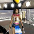
  13. Give credit where credit is due. http://nightlyre.deviantart.com/art/ME3-Garrus-Cosplay-Brushing-up-on-skills-377703605 Her cosplay is Garrus is absolutely amazing, though. Author's descrip explains why the book's picture has nothing to do with calibrating. Haha just noticed the consensus building handbook next to her shoulder on the right. The geth must be nearby.
×
×
  • Create New...