

Szico VII
-
Posts
1,054 -
Joined
-
Last visited
Content Type
News Articles
Tutorials
Forums
Downloads
Posts posted by Szico VII
-
-
Some more:
 Langerd, TheWhitePhoenix, Asgarath83 and 2 others like this
 -
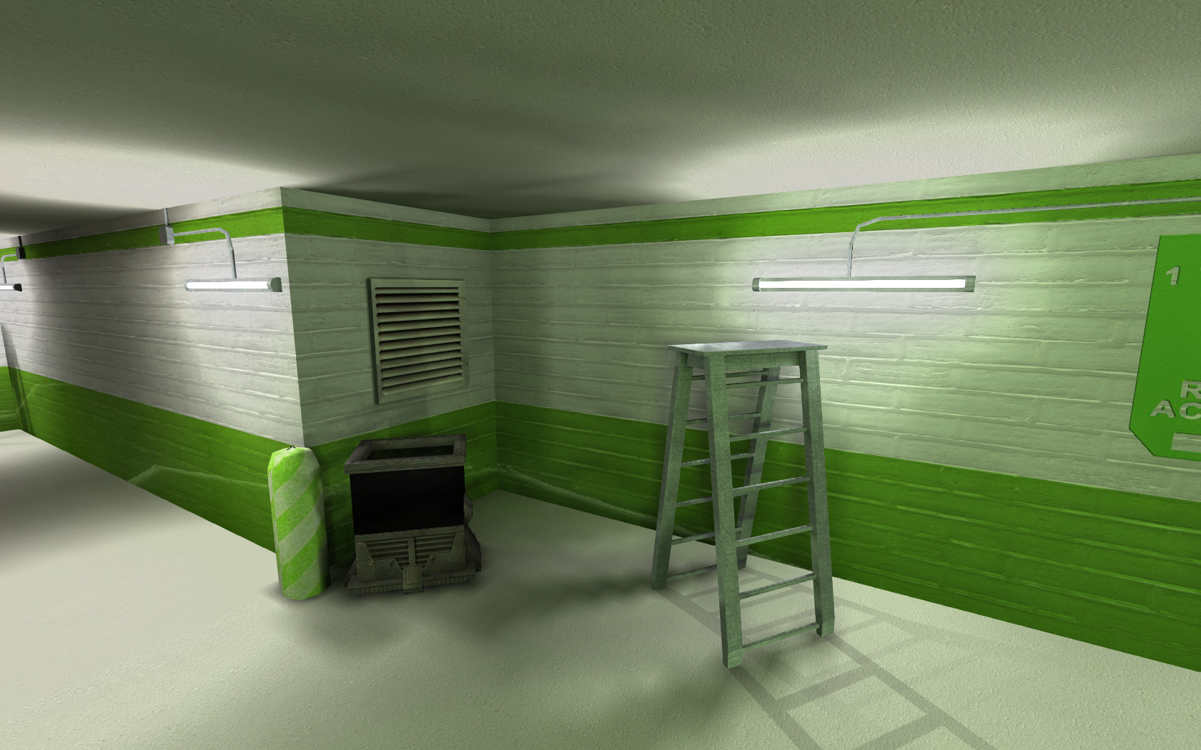
Just to put some ideas here - all currently in baseJA.
therfiles, Circa, TheWhitePhoenix and 3 others like this -
Looking through those screens I am very impressed how you have updated the original map but improved the architecture and design - very nice work, I am looking forward to it!
A lot of the textures look flat and basic yet the use on different brushes with the lighting makes it all look right - I hope ingame it is just as good!
Langerd, TheWhitePhoenix, AngelModder and 1 other like this -
Someone on Steam reminded me of this and found it on old hard drive - so I have submitted what I had finished as an unfinished file to JKHub.
I found that I cant get rend2 to work (Xycaleths latest buildbot) with OpenJk without it a)crashing b)not working or c) breaking fog and other effects so there's no rend2 support for it unfortunately. Source files included
-
Well thats just plain old reflection isnt it?
-
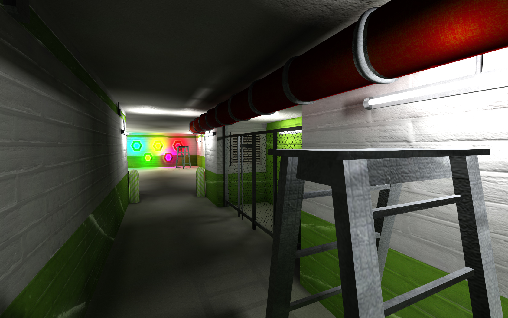
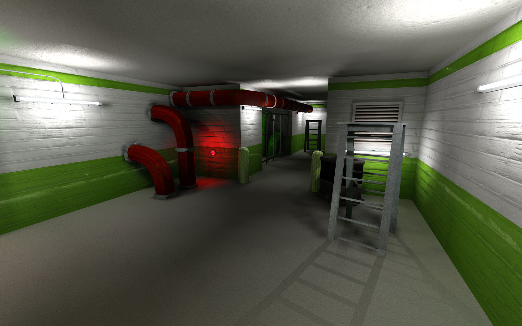
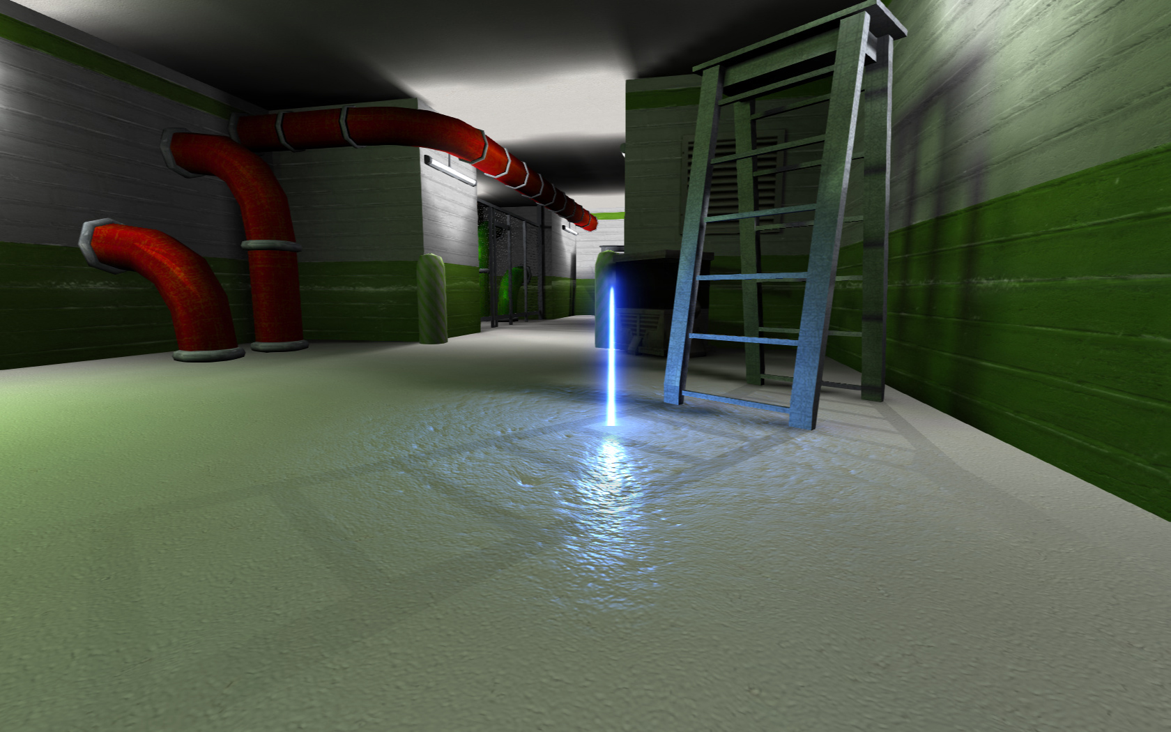
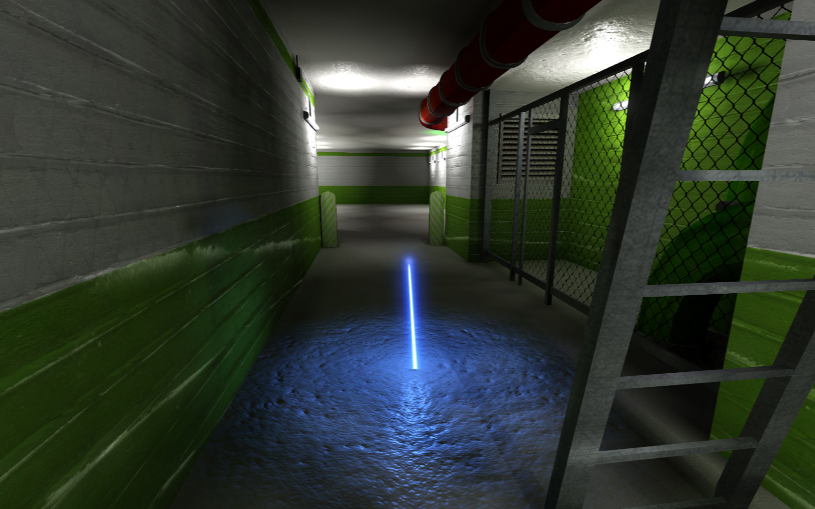
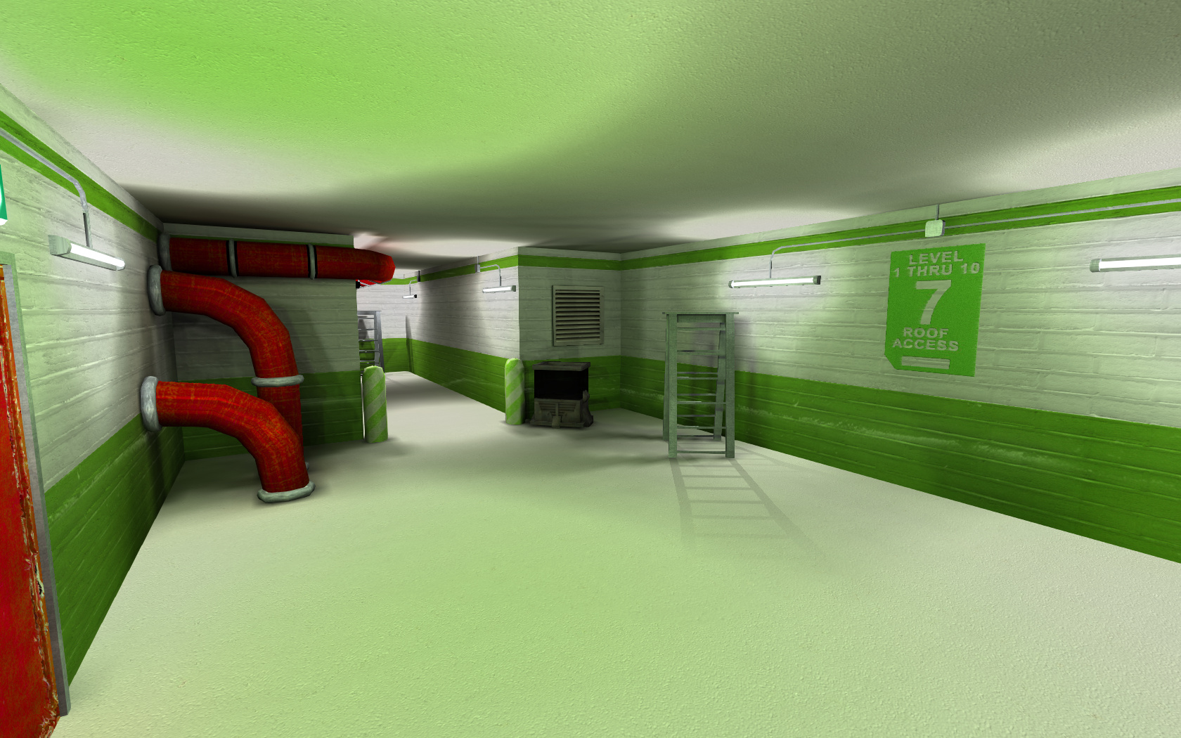
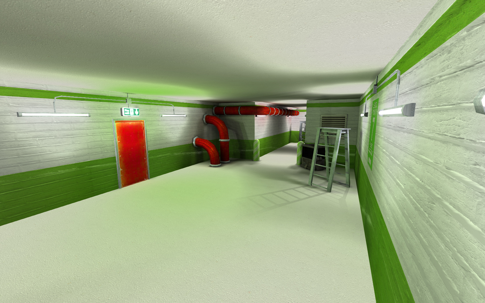
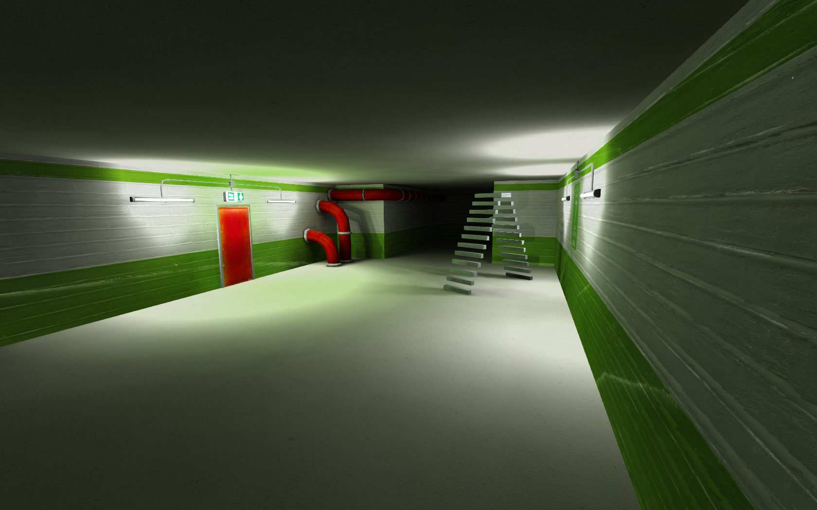
Yeah here it is - played with r_hdr 1 and r_parallaxmapping 1. You can remove the effect lighting (fx_runners) and recompile if you wish). Everything else is entity lit.
-
@@Xycaleth - Map is finished, if it has what you need for testing.
Dont know how I missed your post. That looks great, Szico!
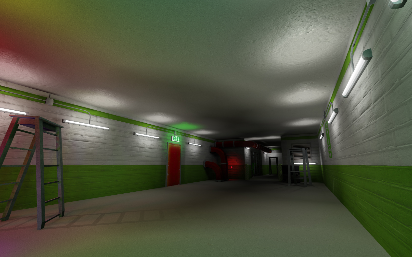
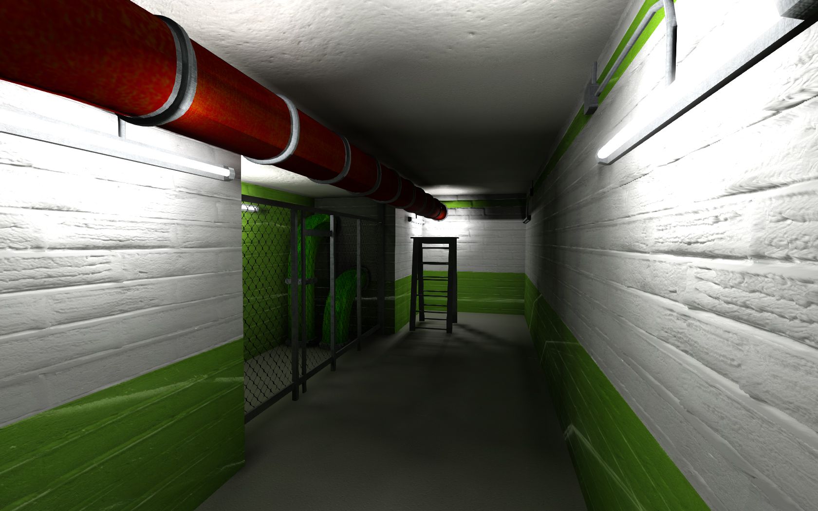
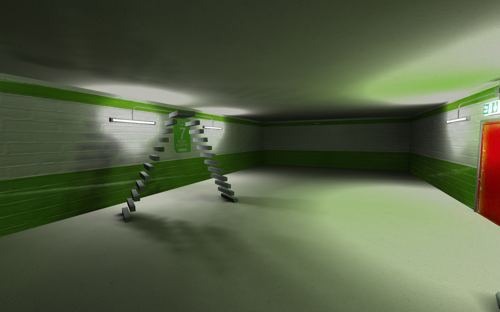
something that irks me about q3map2 is that it doesn't bleed the colours from textures on to surrounding surfaces. You would expect some of the red and green on the pipes and walls to show up on the floor and walls but it doesn't. I guess it saves on having to compile the map every time you change the textures but it would look so much better if it could do that Yeah, isn't that called subsurface scattering?
http://www.youtube.com/watch?v=Jaqqwk2UaC0Circa, Archangel35757, Mark Lubbers and 4 others like this -
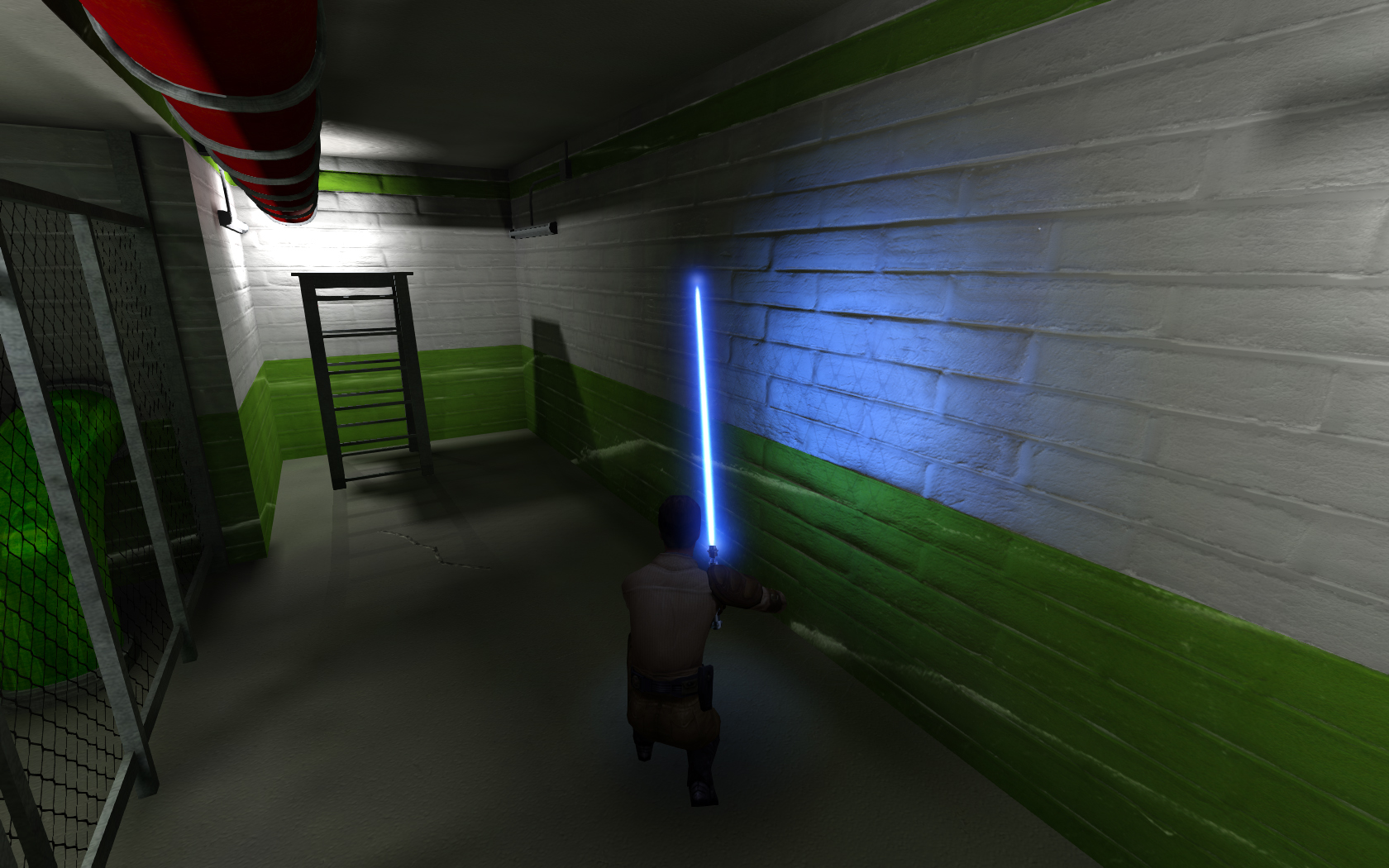
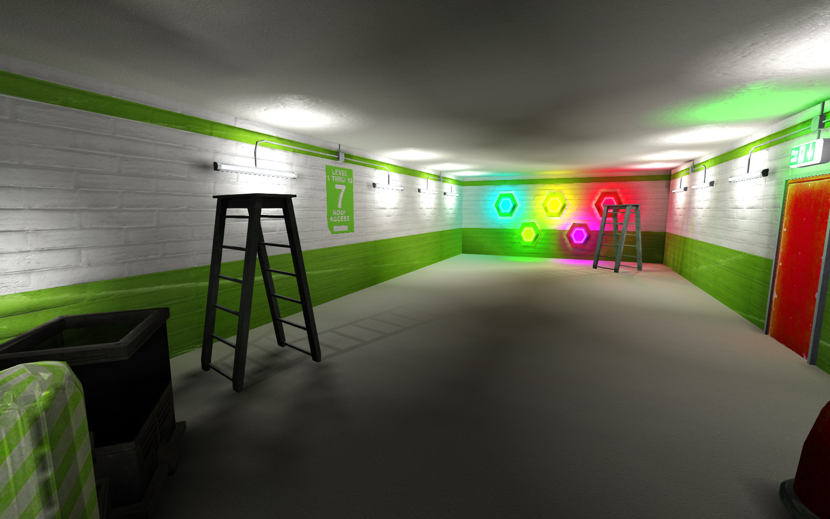
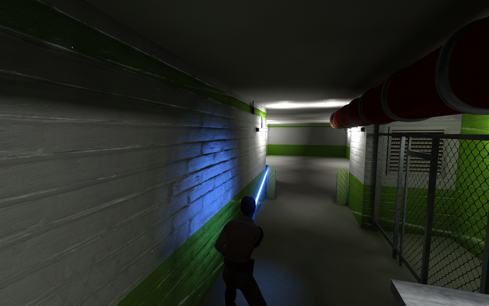
Well the ladder shadow and the grate shadow do have "fake" shadows made with textures and alpha maps (easily removed).
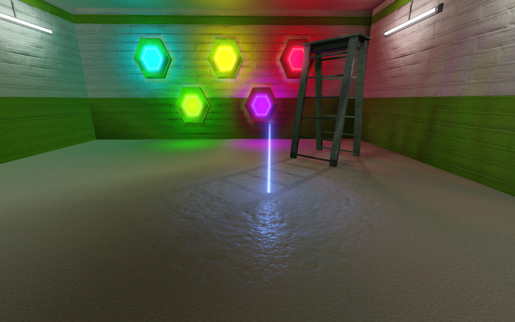
But dear god - using dynamic lights adds SO much - i didn't think the spec of bump maps were actually doing much until put lightsaber near them! I faked more with effect (fx_runners) but does lag the framerate
-
Have you ever used IES light data in alpha channels?
No, never have - this is just using photoshop
Xycaleth likes this -
Okay I just erased the old openjk.vfg and problem was fixed. Started making something
Xycaleth and Archangel35757 like this -
I tried the newest rend2 yesterday and it made all the lighting incredibly grainy - didnt look at all the same as when I last used it
-
Yeah, what do you want in it? And how big? Any structures or just a room?
Archangel35757 likes this -
Hmm. Not sure. If it was something to do with a limit, then possibly.
I suspect it was a problem with q3map2 not being able to keep all the calculations in its memory properly
-
I wonder if that lightmap compilation issue is fixed?
(The one where if you had a lot of lighting and used complicated things like -samples 3 and low _lightmapscales the whole map would come out borked from a lighting view with odd shaders everywhere)
-
Your Bioshock map was completely indoors right?
Yes but only used shader lighting
I meant I can make a small one quickly with entity lighting for a testbed
what kind of statue model and format MD3 or what?
https://www.youtube.com/watch?v=2f6YDYPkVHU
The two statues at 1:00 (either side) and the big guy at 1:42 (in md3)
And the angel things in the screenshot
-
On the WIP shelf along with moonbase
I needed a model (statue) to continue with the bioshock one and couldnt find an appropriate one alas -
* Limits are much, much, higher. You can now make gigantic maps that are highly detailed at the same time
Would you be able to elaborate?
Might try this for compiling some of my WIPs
Stoiss and Archangel35757 like this -
-
I can confirm Dark XL is much better!
-
Ah okay. Not a fan of the new theme....well, mostly that background image far too clashing
MagSul likes this -
I dont see a new theme>
-
A whiole ago I was hoping someone could point me in the direction of getting q3map2 to work with MOHAA - ydnar stated on his website "in a whirlwind weekend at EA I added support for MOHBT" but Ive never figured out how to use q3map2 for MOHAA maps. - LINK: http://nonasthmatically2.rssing.com/chan-1130926/latest.php
I also despised MOH radiant compared with GTK radiant lol
Smoo likes this -
YES. I tried to get bluicenightfall (i.e verschneit remake) into mohaa but didn't get far
-
You could have an overlay texture as part of the shader with cull twosided and q3map_alphashadow, if youre not worried about extra rendering passes.
 something that irks me about q3map2 is that it doesn't bleed the colours from textures on to surrounding surfaces. You would expect some of the red and green on the pipes and walls to show up on the floor and walls but it doesn't. I guess it saves on having to compile the map every time you change the textures but it would look so much better if it could do that

Szico's Wip Thread
in WIPs, Teasers & Releases
Posted
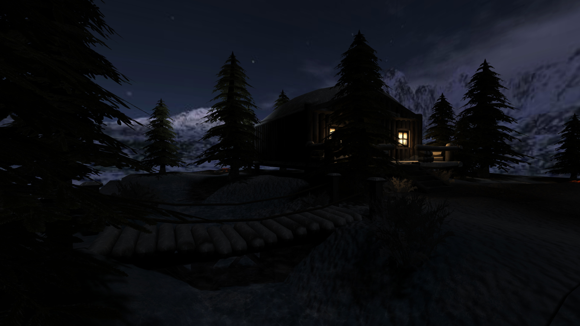
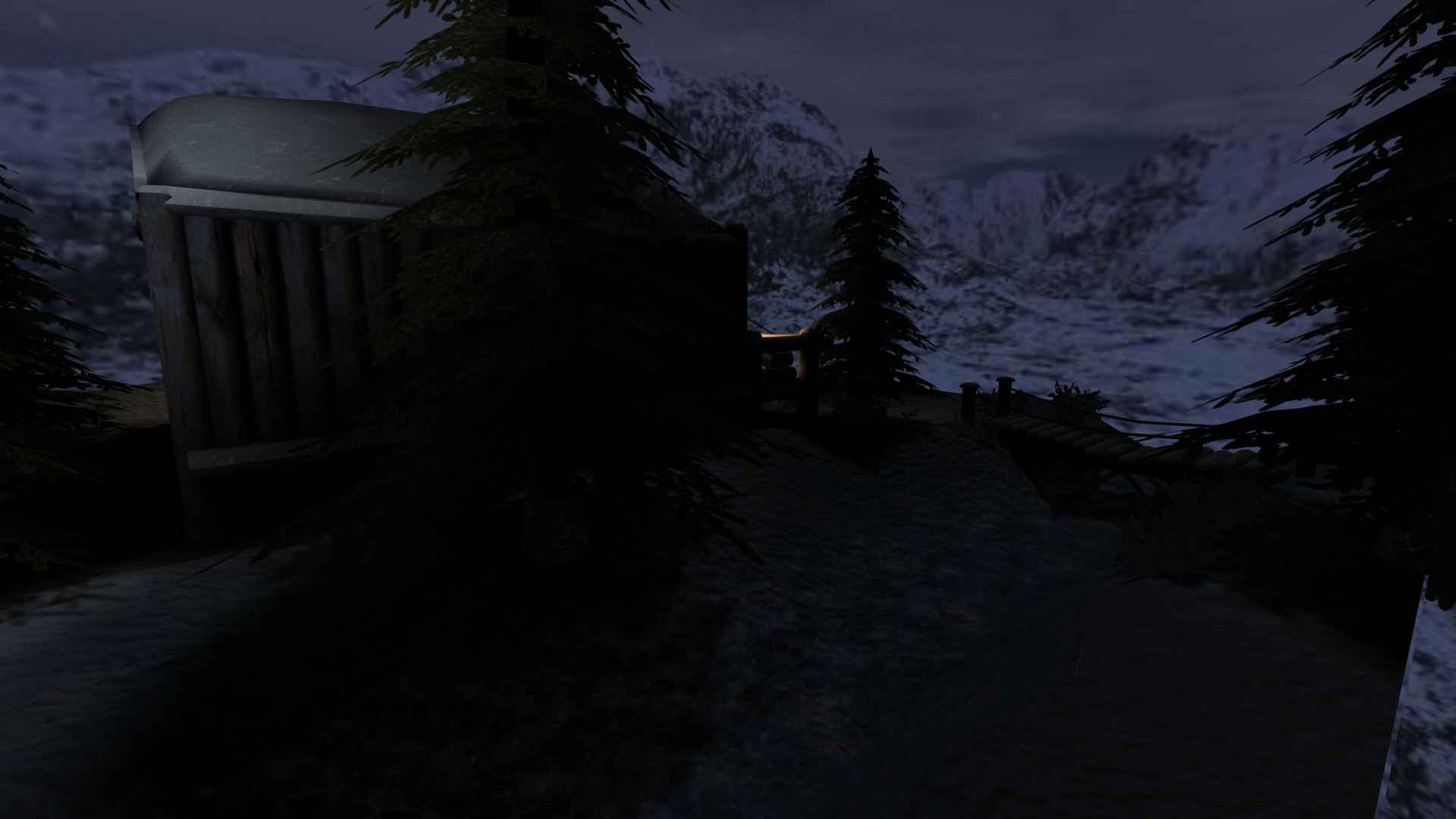
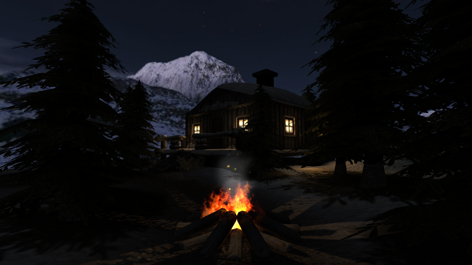
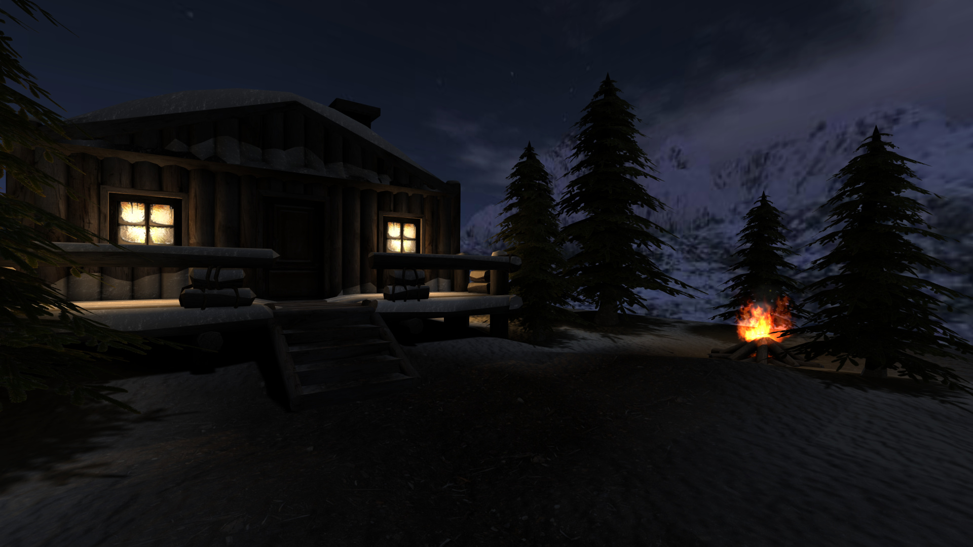
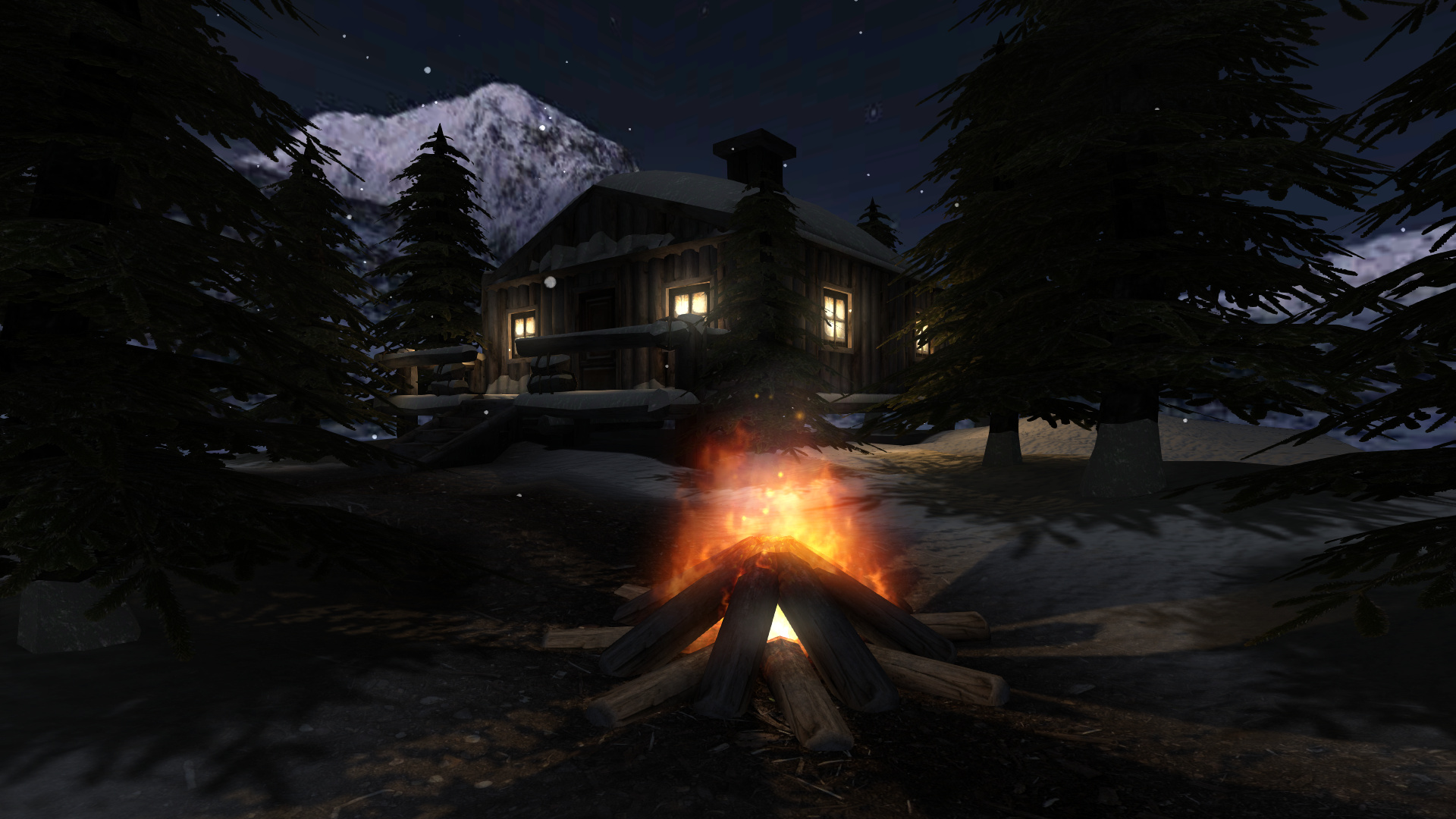
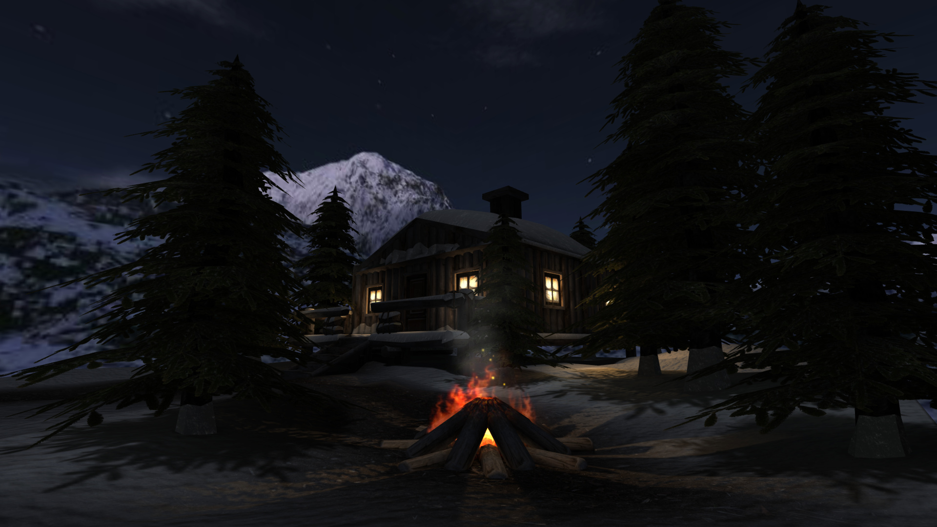
I have not played that game Im afraid! This isnt a horror setting though
I have added a few new bits of river and also updated the cabin, changed the log quality, direction and icicles