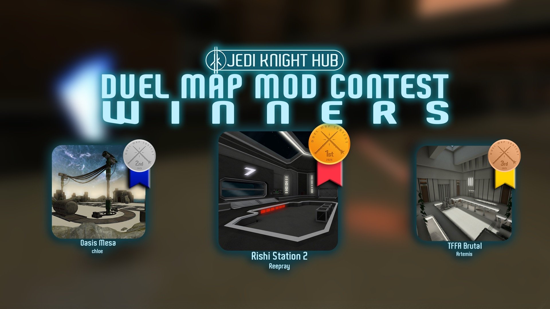
 1st Place Winner Reepray with Rishi Station 2,
  2nd Place Winner chloe with Oasis Mesa, and
  3rd Place Winner Artemis with TFFA Brutal! Amazing submissions by everyone!
This tutorial goes through the steps required to export a new vehicle from Blender into Jedi Academy. It does not teach how to create the model itself.
Before we start make sure you've properly installed the Blender JKA Plugin Suite.
http://jkhub.org/ind...eenshot&id=1413
Blender 2.64+ - Jedi Academy Plugin Suite v0.2.1
The Jedi Academy SDK is also useful as it includes ModView, a Model Viewer for glm/gla files.
Then just create your model as usual. There's plenty of tutorial on that so I'm not going to reiterate. You can even have multiple levels of detail, though some limitations apply. (See the part about the G2 Properties)

But when creating the UV maps you'll have to keep in mind that the GLM format saves UV coordinates per vertex, not per face. So any uv seam on your model has to actually be a split in the model. The easiest way to do this is to also mark any seam as a "Sharp Edge" as well (in the Edge menu opened by Ctrl+E)...


... and use the Edge Split modifier to create the splits there. (Be sure to enable "Sharp Edges" and disable "Edge Angle".)

If the exporter were more clever it could do the splitting automatically, but alas it can't. While we're on the topic of UV maps: Every vertex needs UV coordinates. Every. Single. One. Even those on hidden tag surfaces. (I never said they need to look good, right?) You'll get an error to remind you otherwise.
Next, a word on shading. Jedi Academy basically uses smooth shading on everything. To preview this in Blender, you can enable it for all faces by selecting them all (A) and enabling Smooth Shading (W -> Shade Smooth):
 ->
-> 
So everything will be smoothed. You may not want that, but once again Edge Splitting helps: Just mark any sharp edges as such and use the Edge Split modifier as above.

As above? That's right, any UV seams will inherently not be smoothed on the model, so keep that in mind when choosing the seams.
All this splitting may add a lot of additional vertices. Be careful to stay below the limit of 1000 vertices per mesh that Jedi Academy has and split the mesh where necessary.
As for animations: Jedi Academy's animations are skeleton-based so you'll have to use an Armature. The actual animations you'll need vary from case to case - if you're doing something swoop-like, you won't really need any (you still need to export a one-frame root animation and the model has to be properly rigged), but in my case I've got an x-wing like model with landing gear that has to be folded in/out and turbines that need to rotate into flying position. This is similar to the X-Wing, so I take a look at the X-Wing's animations in ModView. Base your vehicle on existing ones or you might have to code the new behavior. (My VTOL won't have a hover mode, for example - it'll fly like the x-wing.)
Whatever you do, make sure you have a single root bone (i.e. without parent) called "model_root" and there's a proper hierarchy in your skeleton, loose bones will go missing and if there's no model_root animations won't work.

Wing opening is analogous to rotating the turbines, and the gear is just the same, so let's create the animations! The gla files are just one long list of frames, so set the scene up in a way that all the animations are played in a row. Keep in mind that you can play them backwards too, which is used in the x-wing as well. Again, there's plenty of material on skeletal animations in Blender, just refer to that. Feel free to use IK and all kinds of crazy rigs, there shouldn't be any problems as long as you're using a single Armature in the end.
You'll have to write a configuration file describing the animations: Their name, when they start, their duration, the FPS etc. There's a plugin to aid with that, so let's use that. First, we have to mark the beginning of each sequence of the animation. Do this by placing a Marker at the appropriate time in the timeline (M) and renaming it to the desired name (Ctrl+M). Also make sure the animation duration is set correctly, which it will have to be for the export as well. Just leave out the backwards playing animations, this is a rough first version.


Then use the animation marker exporter to export it to a file called animation.cfg, which should then look somewhat like this:
// Animation Data generated from Blender Markers
// name start length loop fps
BOTH_GEARS_OPEN 0 15 0 24
BOTH_WINGS_OPEN 15 22 0 24
Edit that to fill in the missing sequences, using the one from the vehicle you're basing your new one on for reference. This is what I ended up with:
// Animation Data generated from Blender Markers
// name start length loop fps
BOTH_GEARS_OPEN 0 15 0 20
BOTH_GEARS_CLOSE 0 15 0 -20
BOTH_WINGS_OPEN 15 21 0 20
BOTH_WINGS_CLOSE 15 21 0 -20
BOTH_VS_IDLE 14 1 0 20
ROOT 14 1 0 20
There's a special kind of surfaces in glm files: Tags. They signify positions, and in vehicles they can be used to define where the exhaust effect should be played, where the muzzles are (i.e. where shots come from) and, for vehicles like swoops, where the player should be placed. This could be done pretty well using an Empty in Blender, but those can't be properly weighted to a skeleton so surfaces are used instead. It works like this: The origin is at vertex 2, the X-axis towards vertex 0 and the Y-Axis towards vertex 1. In Blender there's no built-in way of displaying the indices that I'm aware of so take care to create them in the right order.

Raven has the guideline of making the X Axis short and the Y Axis long, but they too occasionally screw up (take a look at the X-Wing's tags, for example.) Take a look at your exported model in ModView to make sure your tags are correct. The exhaust effects and shots in Jedi Academy go in the Y- direction, so place your tags accordingly. (Again, feel free to look at existing models for reference, for example in ModView, which also allows display of vertex indices.) Keep in mind that tags, too, need to be UV mapped, although they will be hidden.
The tags for the muzzles are called *muzzle1, *muzzle2 and so on, while the exhaust ones are (predictably) called *exhaust1, *exhaust2 etc. Again, ModView is your friend for finding out the right names.
But how will the exporter know which surfaces are Tags? You'll have to tell it! You might've noticed the "Add G2 Properties" button in the object settings. Press it and you'll be able to set some glm specific settings.


You will have to add these properties to all your objects! Why? Because glm files can have multiple Levels of Detail (LOD), so to be able to match them they need the same name across the board, and that's done using the "name" property. You also have to define the material to be used on this object, using the "shader" setting. Multi-material objects are not supported, so you may have to split your meshes. Also keep in mind that the same materials have to be used across the different LODs! The settings from LOD 0 (the most detailed one) are the ones that actually count, for the other levels only name is relevant. (And it has to match the name of an object on LOD 0! You can't add new objects on lower LODs!) The "Tag" checkbox is to tell the exporter what's a tag, and the "off" checkbox is supposed to be used for hidden surfaces, but ModView instead looks for names ending in "_off" and Jedi Academy uses the skin files instead.
You also have to set up a proper hierarchy. In playermodels, this is also used for dismemberment, in case of vehicles it's mostly mosmetic. (Although I think they can lose parts when exploding, too? Someone investigate!) The important thing is that the hierarchy is used for LODs, and all you need to know is this:
At the top level, you need to have a scene_root object. (Add Object adds an Empty placeholder perfect for this.) All objects will be exported in scene_root's space, i.e. if you scale scene_root down to 10% scale you can work at 10% scale and still export full-size. Keep that in mind in case you've imported a player model to get the scale of your model right: Use the same scale in your scene_root as you used during the import!
Your armature has to be a child of scene_root and needs to be called skeleton_root (both object and armature). However, if you've imported a playermodel for scale, make sure your armature is not called skeleton_root or the importer will try to use that armature for the imported model! While we're on the topic of scale, don't scale your bones! There's no support for scaling in gla files since that's hardly ever necessary.
For each LOD, you'll then need another (Empty) object, called "model_root_0" (or "model_root_1" for LOD 1 (less detailed than 0) and so on). This object should have exactly one child, the root object of the exported hierarchy. (For Raven's models this is an extra surface called "stupidtriangle" that they needed due to their inferior exporter.  ) Below that, it's up to you unless you need dismemberment, but every part has to be in the hierarchy somewhere.
Here's what my hierarchy looks like:

Remember that the names here are not the ones used for export, the exporter uses the ones from the G2 Properties.
The last thing to do before exporting - and you'll likely only want to do this just before exporting since it makes editing the model later harder - is to apply all the modifier except for the Armature one and to triangulate all the meshes (Ctrl+T).


And then it's just a matter of exporting with the right setting. First the gla, since the glm will have to reference it. The important thing here is to clear the "gla reference" field. If we were creating new animations for an existing skeleton we'd enter its path here, but since we're creating a completely new skeleton we'll leave it empty. If you're not working directly within your base/mod folder, you may have to setup "Base Path" as well, refer to the manual in that case.

And then the glm. Make sure to point it to the gla you just exported in the ".gla name" field, omitting the ".gla" extension. The file has to be called model.glm.

And then it's just a matter of copying the appropriate .veh file in ext_data/vehicles and an .npc file in ext_data/npcs and adjusting them.


Here are the files I ended up with, including the .blend files before and after applying the modifiers. (They may differ in some other ways, too, I was playing around a lot while writing the tutorial.) Since this is mostly about the model the .veh file isn't quite perfect and I didn't create unique graphics for the UI either.
mrw_vtol.pk3


Recommended Comments
There are no comments to display.
Create an account or sign in to comment
You need to be a member in order to leave a comment
Create an account
Sign up for a new account in our community. It's easy!
Register a new accountSign in
Already have an account? Sign in here.
Sign In Now