 1st Place Winner Reepray with Rishi Station 2,
  2nd Place Winner chloe with Oasis Mesa, and
  3rd Place Winner Artemis with TFFA Brutal! Amazing submissions by everyone!


This simple but comprehensive tutorial will teach you how to make a very basic sword model from generic shapes. It is ideal for learning to make weapons for video game modding.
Originally written by Inyri Forge
Tools you will need
NOTE: This tutorial was written with 3DS Max in mind. Some parts may not be compatible with GMAX - I can't say for certain because I don't use it and don't know what functions it doesn't have.
See the attached key below to find all important buttons/functions listed in this tutorial:

This tutorial will cover all aspects of both modelling and skinning a very simple sword - a Roman gladius. This sword will need the following basic shapes: a plane (or box), two spheres, and a cylinder. That's right! You can make a sword out of just these basic shapes. I purposely picked a very simple design to begin with. It's never good to try and learn to do something by starting out with something complicated.
The first thing we want to do is find a good reference picture. I've already done this for us by using a quick google search. Searching google is one of the easiest ways to find good reference pictures without having to do much work yourself. For self-concepts or less common models you may have to draw your own references. If this is the case you just want to make sure your reference is as straight as possible (you may even want to open the image with your image editing software and rotate it until it is as straight as you can get it). This will help in the modeling process.
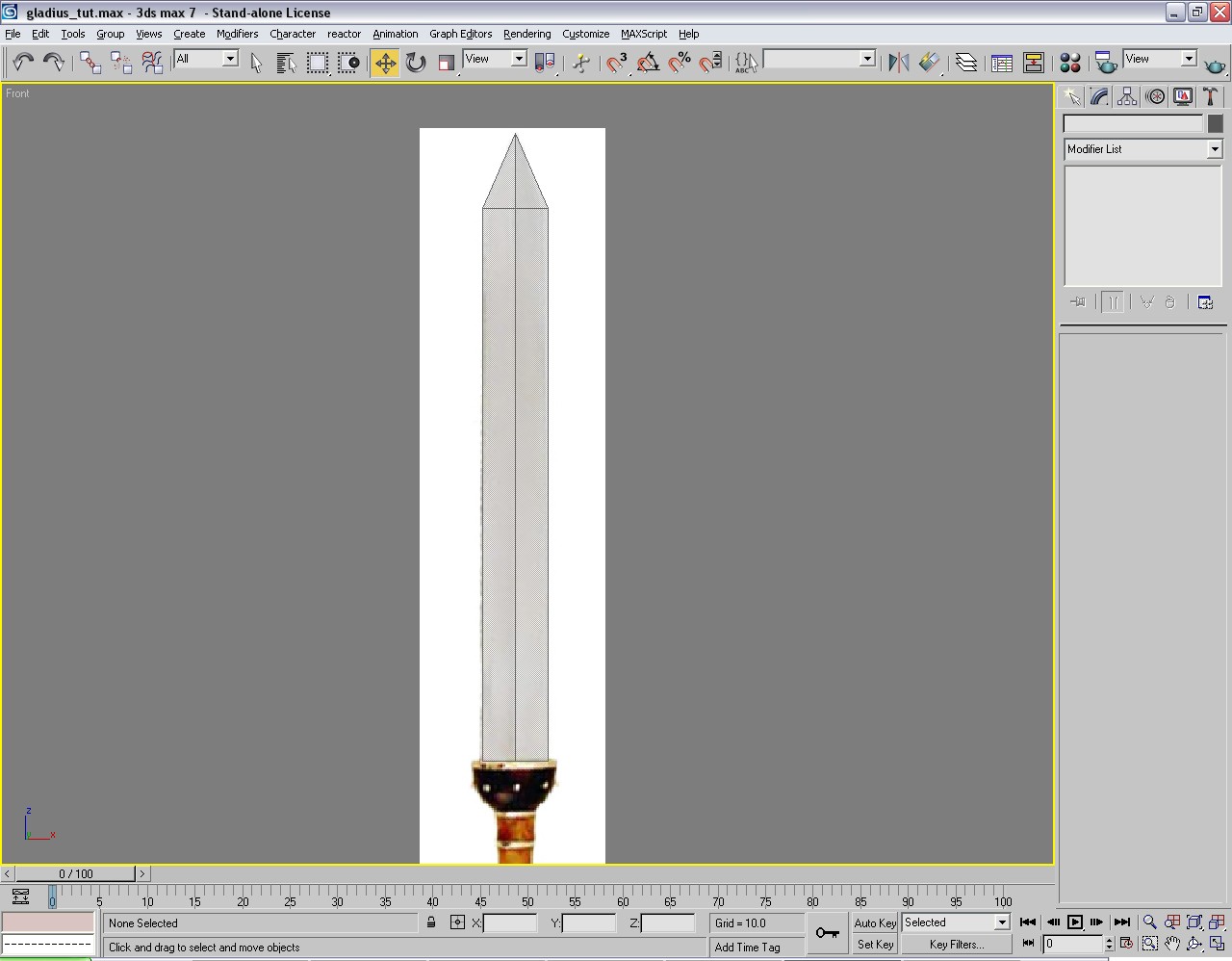
So here is our base reference image:
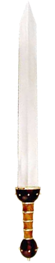
As you can see, this image is only from the front. We will have to "guess" what it looks like from the side. It is okay to assume that the hilt portion is either perfectly round or slightly ovular - whether you want your grip to be round or an oval will be up to you - it really doesn't matter. I am guessing both the sphere on the bottom and the guard separating the hilt and blade are also round. This will be important later.
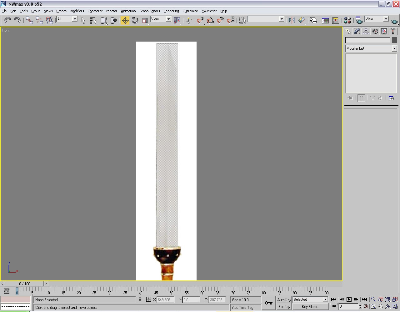
The first thing we want to do is open up 3DS Max or GMAX and start out with a fresh scene. Pick a viewport - I usually use the front viewport - and hit ALT + B. This will bring up the viewport background window. What we want to do is add our base image as our viewport background. Find it, wherever you saved it on your hard drive, then under Aspect Ratio select Match Bitmap. Just to the right, make sure both Display Background and Lock Zoom/Pan are selected. Click OK.
So now we should see our gladius image on the background of our viewport. If you find the grid distracting, as I usually do, you can turn it off by right clicking the viewport name and selecting Show Grid. This will toggle the grid off. There, now I can see my reference better! At this point I would zoom in to your selected viewport by hitting the Maximize Viewport Toggle button in the very bottom right. You will probably also want to zoom out by using your mouse scroller.
So now what? We have our image, but how do we start? First of all, make sure yo'ure in the create tab. I use a plane method to make all my sword blades, so I don't have to worry about two layers of vertices, but you can just as easily use a box and skip the extrude step I will get to later. This tutorial will go over the plane method. Make a plane roughly the size of your blade. Don't worry if it's not perfect. Once you have made your plane, you may want to change the viewport rendering to Smooth + Hilights. Find this in the same place as Show Grid. Now hit escape to deselect the plane tool and select your plane. Hit ALT + X to go into x-ray mode and F4 to show your edges. If you see lots of edges, go into the modify tab and change your length/width segments to one.
MODELER'S HINT! It's always easier to add edges than remove them! If in doubt, use less detail than you need. You can always add more later, but removing detail can be a pain!
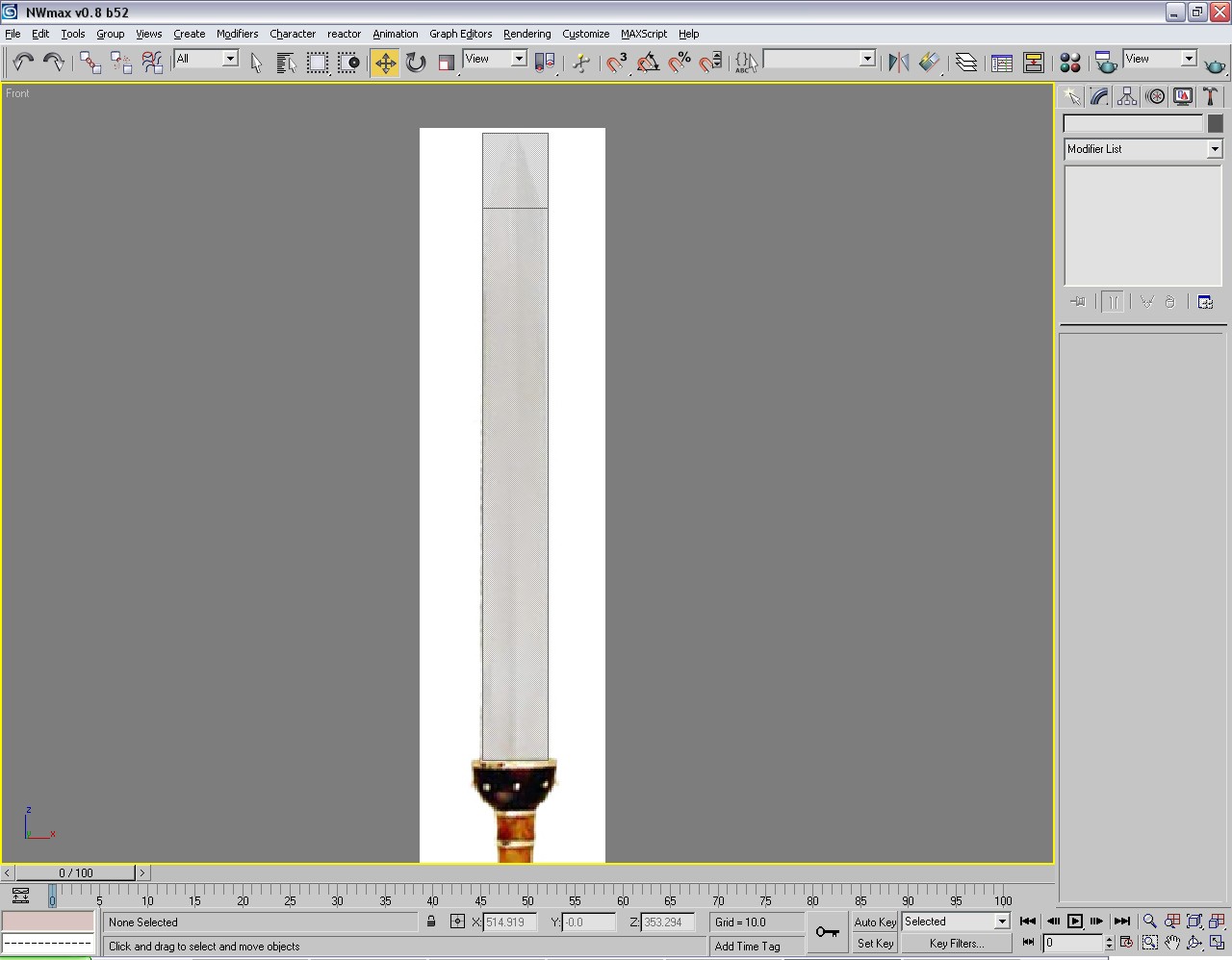
So now your viewport should look something like this:
What we want to do now is right click on the plane, go down to Convert To and chose Editable Poly. This will bring up the Editable Poly Roll-out. Select the Edge Tool and select the two long edges. Right click and select Connect. You should now see an edge in roughly the middle of the blade. Using the Move tool, drag it up to where the blade first begins to narrow.
At this point, your viewport should look like this:
Now we want to select all three of the short edges and hit Connect. This should draw a line right down the middle. Now I will teach you a time-saving technique for use with symmetrical objects. Select the Vertex tool and delete all the vertices to the right of that center line. That will destroy the right half of your plane. Unselect the vertext tool and select your plane. Hit the Mirror button and make sure it it set to X. Then under Clone Selection choose Instance. This will copy the right half of your blade to the left half, so whatever you do to one side will be mirrored on the other. Handy, huh?
Now select the left side again, and select the vertex tool. We will now use the Target Weld tool. Select the target weld button and click on the top left vertex. Now click on the top middle vertex, where the point of the sword is. Now our plane looks a little more like it's supposed to!
You'll notice the shape isn't quite right, as the gladius narrows a bit at the top. No worries! With the vertex tool, select the top right vertex (not the point of the sword!) and with the move tool move it to the right until it matches the reference image. You may also have to move the bottom left vertex out as well. Now you should know enough about the basic tools to be able to do this, though! Move the outer vertices around until you're happy with the general shape.
So now what do we do? All we have is a flat plane. Now comes the fun part. The first thing we want to do is combine the two halves of our sword to avoid headaches later on. Because the right side is an instance, we can't attach them directly. So what do we do? Delete it! Repeat the process of making the instance, but this time chose to copy it as a copy. Now you can choose Attach from your modify panel and click on the other side of the blade. To reduce the vertex count, use the vertext tool, select all vertices, and click Weld. With the default number it should weld all the middle vertices without welding any vertices you don't want to weld.
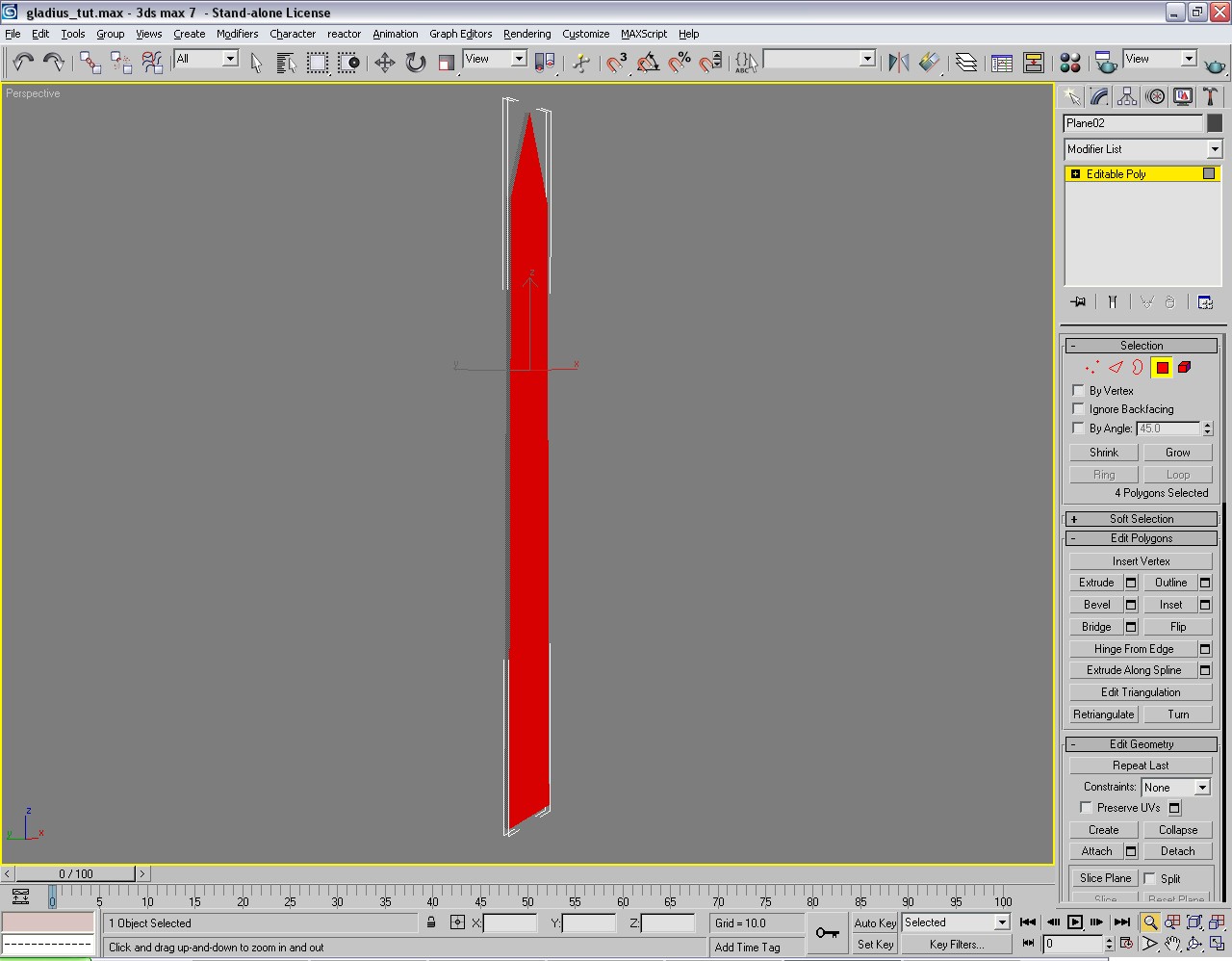
Now that our blade is complete again, use the Polygon tool and select all the faces of your blade. There are only four, so it's not a big hassle. Just hit CTRL + A to select all. Now hit Extrude in your roll-out. Don't see a difference, do you? Now we'll need to go to a different viewport to see what we're doing. Hit Cancel and press the P button on your keyboard. This will send us to the Perspective viewport. Don't worry that your base image is gone - it's still on your other viewport. Zoom out so you can see your whole model and use the Viewport Rotate button to get a good angle on your blade so you can see both the front and side. With all faces still selected, once again hit Extrude. Now we can see what's happening! This will only be one side of your blade, so the default 10 should be okay. We can always increase it later if we need to. Click OK.
So our sword now should look like this:
Now we're going to use the Target Weld tool again to make the blade sharp - nobody wants to use a dull blade! Weld the vertices of the front to the back, leaving the middle vertices where they are - you have nothing to weld them to anyway! This is easiest to do in perspective mode. Remember, you can turn edges on here too by hitting F4.
Here's another trick, to make sure your blade looks sharp. With the Polygon Tool select the faces of one side of the blade - right or left. Scroll down in the rollout until you see Smoothing Groups. Underneath this will be buttons numbered 1 to 32. 1 should be hilighted in yellow. Click it so it is grey, then click the 2 next to it so that the 2 is yellow. This will cause one side of your blade to have a different smoothing group than the other, making it have a hard edge. This will help your blade to look a bit harder. For smoothed blades you'll want to forgo this step.
Now to make the back side of our blade we will once again employ the mirroring technique, but this time choose Y as your axis. You can mirror as a copy if you like and attach the front to the back if you're sure you aren't going to make any more changes. If you think you might alter your blade later, copy it as an instance again. You can skip the welding phase here also if you like. This will keep the blade from smoothing around the edges. For swords with higher vertex counts you will want to weld them and apply different smoothing groups to either side, but this sword has so few polies in the blade that it is unnecessary.
So now our blade is done! Phew! Let's move on to the hilt. Hit F to go back to your front viewport. Use the Pan tool to get a good view of the hilt area and zoom in if you need to. We will make the hilt before we make the guard. From the Create tab select Cylinder. A section will pop up called Parameters with a bunch of options. Change the Height Segments to 1 and the Sides to 8. Anywhere from 8 to 12 sides should be sufficient for current gaming purposes (the game engine will smooth these faces and you will not see a difference even if you use additional edges). Using more sides than that is simply wasteful.
Put your mouse cursor at roughly the middle of the hilt and click, dragging ds until the edge of the cylinder is close to the edge of the hilt in the picture. Drag the mouse a little bit and click again - this determines the height of the cylinder. Since you can't see how long you made it, we'll worry about changing it later. Hit escape to deselect the cylinder tool. Once again hit ALT + X to put this cylinder in x-ray mode.
The cylinder isn't facing the right direction, so we'll need to rotate it. If you have 3DSMax you can use the Angle Snap Toggle to make sure you rotate it exactly 90 degrees. If you have GMAX you'll just have to be a little more careful, as I'm told it lacks this function. Click the Rotate tool and rotate the cylinder 90 degrees. That should look more like a hilt! Move the cylinder up or down and use the Scale tool to scale it only up and down (select just the green part and pull it up or down, depending on how you rotated your cylinder). Position the cylinder so it approximately covers the hilt. To compensate for our hilt guard and pommel section we will need to make it a little bit longer on both ends. I forgot to tell you to do this for the blade, so we'll fix that later.
Your model should look something like this at this point:
You can see our hilt isn't quite the right shape, as we did with the blade, change the cylinder to an editable poly. Using the vertex tool, select all of the bottom vertices and scale them (you can scale in all directions this time by clicking the center of the yellow portion and dragging) until the are about the width of the bottom of the hilt in the picture. Do the same with the top.
Now we have this:

Much better! Our hilt is done! Wasn't that easy? So now we have to do the pommel and the hilt guard. This'll be a little bit more complicated, but not too bad. For these we will use the sphere tool.
The first thing we want to do is fix our blade. It isn't quite long enough right now, so we want to drag the bottom verts down so they're just overlapping the hilt guard in our picture. This will ensure our model doesn't have any holes. Overlapping objects isn't a bad thing. In fact it is often the easiest way to make sure your model doesn't have any gaping holes in it!
Now select the Sphere tool from the Create tab. Change its parameters so the Segments are about 10 or 12. Twelve segments will be much easier to work with for our purposes. To get the sphere to match our reference, place the cursor near the middle of the very bottom of our blade, click, and drag. If it doesn't match up with the picture, use the move tool to reposition it. Remember to put it in x-ray mode! To make things easier for ourselves, let's rotate this sphere 90 degrees up so that it has a straight line across the middle, where our hilt guard and blade will meet. It's a good thing we picked 12 sides, because the mid line falls right where we want it to! Scale the sphere to the left and right if you need to, then convert it to an editable poly. Delete all the vertices above the center line.
You should have this:

Now if you look at this in perspective mode you'll see we have a problem. Deleting those vertices left us with a hole! In Polygon mode, select Create. Now click on each vertex in order around the top of the half-sphere. This will create a large face which will be the top of our hilt guard. Our hilt guard is done!
Now for the easy part - the pommel. I could explain a complicated way, which involves attaching it to the hilt, yadda yadda yadda, but doing that is really unnecessary and will only make UV mapping it more difficult, so we're just going to leave it unattached.
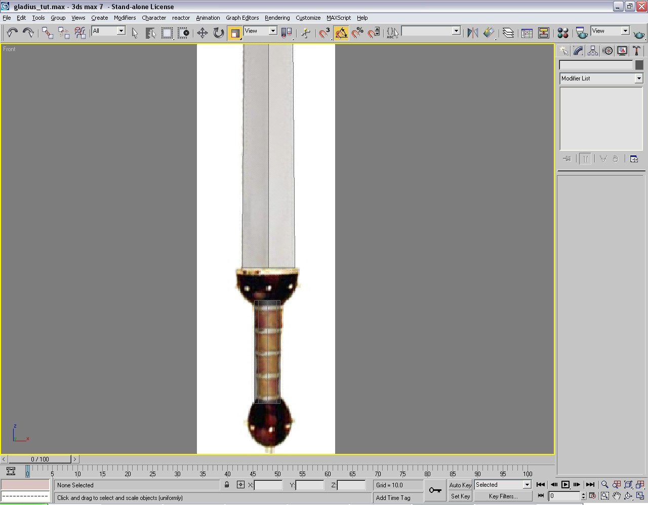
Once again select the Sphere tool with the same parameters are our hiltguard. Click on the center of our pommel and drag. Scale the sphere up, down, left or right until you get the right shape. Voila! Done! Before we move on, you may want to go into perspective mode and make sure your hiltguard and pommel aren't elongated from front to back. If they are, scale them appropriately.
Here is our finished sword model:


Recommended Comments
There are no comments to display.
Create an account or sign in to comment
You need to be a member in order to leave a comment
Create an account
Sign up for a new account in our community. It's easy!
Register a new accountSign in
Already have an account? Sign in here.
Sign In Now