
AshuraDX
-
Posts
2,319 -
Joined
-
Last visited
Content Type
Profiles
News Articles
Tutorials
Forums
Downloads
Posts posted by AshuraDX
-
-
Actually it's the damn jka bones that suck, jko has bones for all 5 fingers and toe bones which allow for much higher fidelity in animations.
this video shows how to convert a jka model to jk2. If you reverse these steps, you should be able to get it working.
mrwonko likes this -

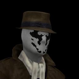
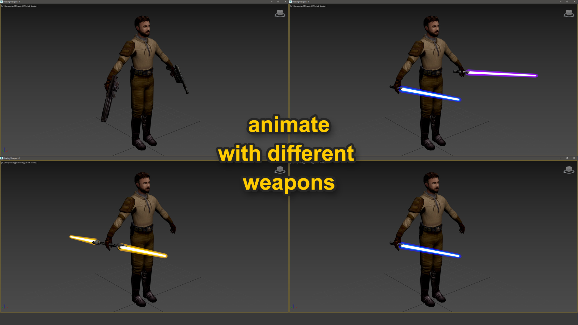
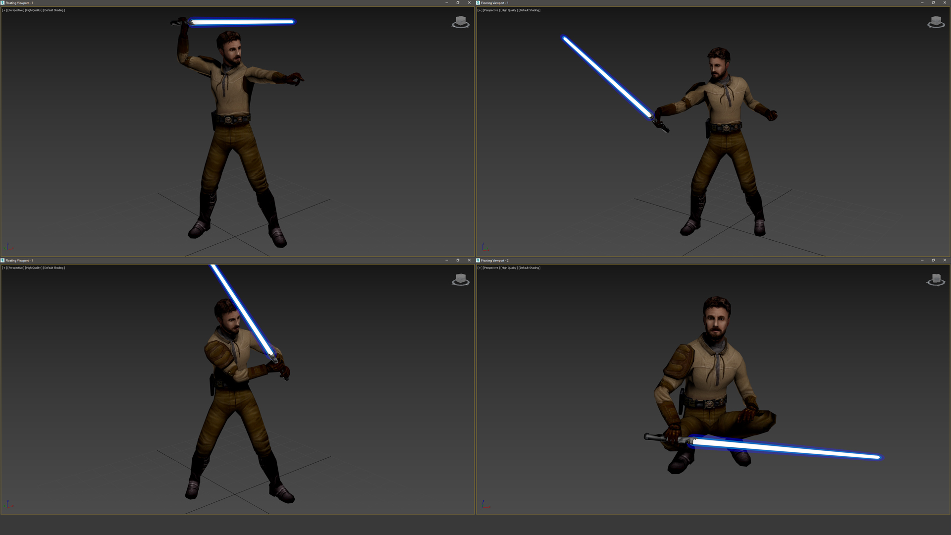
This is something that I've been working on since like 2017. But I finally got around to rebuilding this thing for the third time - this time properly and with all bones for Jedi Academy, Jedi Outcast and even Soldier of Fortune 2.
Most of you are probably like "What the Hell is this?", so let me explain:What is CAT and what can I do with it?
CAT Is a very versatile Rigging and Animation System for 3ds Max. It allows you to quickly and comfortably make high quality Animations, after setting up a Rig that is equally quick to build. This Video (and this Channel in General) explain what CAT is and what it can do really well:
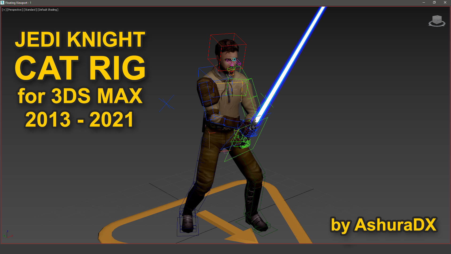
This rig comes in a 3ds max scene with the original Jedi Knight Game bones constrained to it. This means that when you move any part of the rig, the bones of the character move accordingly. It is also organized in layers and comes with a couple of useful premade selection sets to streamline animating and exporting your animations to the game.
How do I use it?
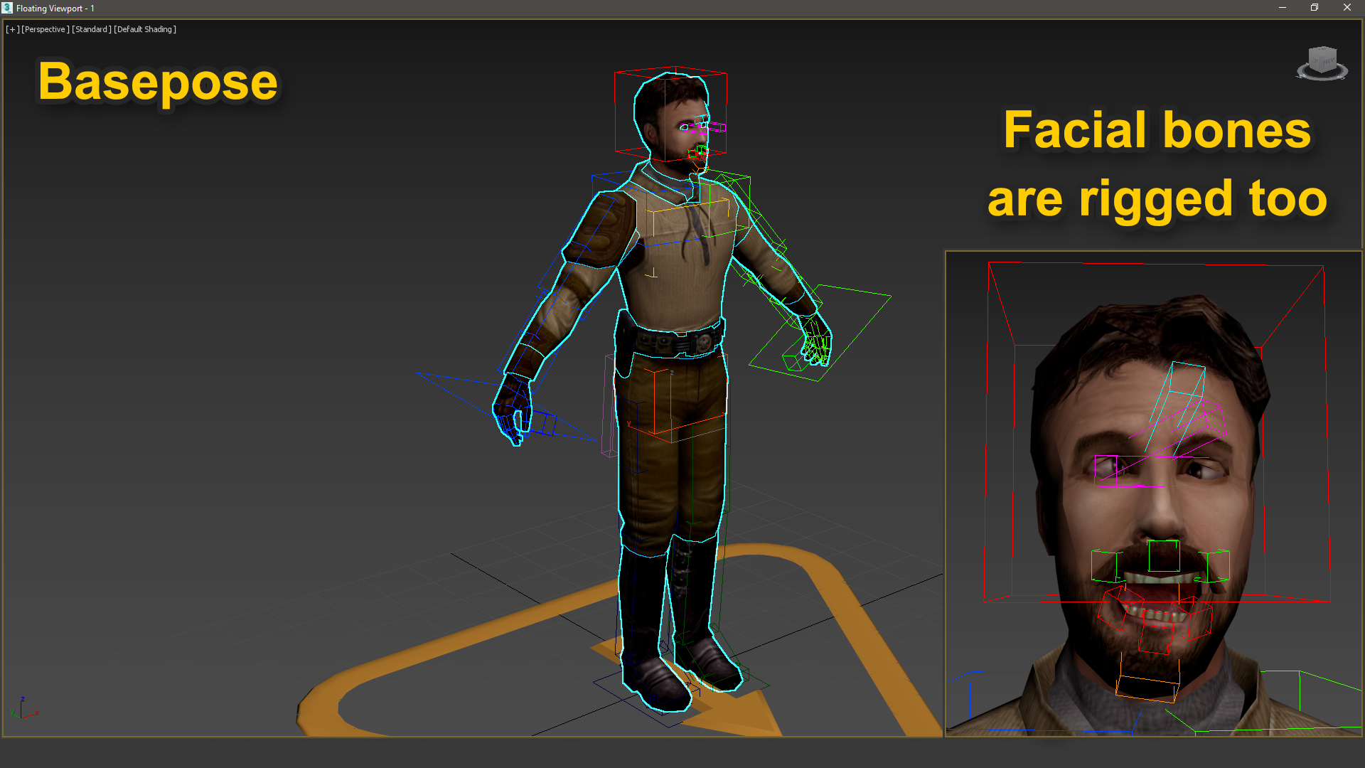
To export animations and get them ingame you will need the Jedi Academy SDK Repack and the dotXSI Exporter for your version of 3ds max. (I linked the exporter for 3ds max 2021 underneath - check the authors other uploads for alternate versions)
When CAN I use it?
The file has already been uploaded and approved here on JKHub and I hope to get a tutorial written up and recorded until next weekend. WC3Tutorial from the JKCommunity Discord, who has been Alpha-Testing the initial Version of the Rig heavily, might beat me to recording a tutorial - if that happens I'll link it here. I'd be happy to hear any questions you might have upfront that might help make the tutorial better and easier to understand.
If you fancy messing around with this rig before the tutorial is up - don't be shy to reach out to WC3Tutorial or me on the JK Community Discord #modding channel.
Some more pictures
-
Which Version of radiant?
1.4 and 1.5 don't quite work on Windows 10 afaik.
Try Netradiant or GTK Radiant 1.6.
@mjt has written a Tutorial on setting up Netradiant
-
A possibly quicker solution might be to flip the normals of the tag triangle. The orientation of the tag is determined b the order the vertices are in, same for the normal direction. So by flipping the normal direction you can rotate a tag by 180°
-
Hey @Rvix,
two answers for two problems:
The first is likely due to a bug in the importer, it seems to have reordered the vertices in the tags which can cause this behaviour. Flipping the normals on tags using a normal modifier and checking the flip option might do the trick already.
If it doesn't I can send you a script (later, after work) that generates a fresh set of tags in the proper orientation and links them to the model - provided the naming conventions recommended for jka models are held true by it.
For the other issue, that looks like non-zero'd transforms. Is the pivot set to 0,0,0 and aligned to world? And is the object scale at 100,100,100?
Feel free to @me for any 3ds max related questions
-
Sorry, got to call this Stream off. Feeling a bit under the weather today.
-
You discovered that patches change their level of detail based on distance.
You can use -patchmeta in your bsp stage to force a static lod on them.
There are also ways to force a higher subdivision level on them via entity keys iirc, but I'll have to do some digging to find them. @mjt might know more.
NAB622 and Plague-Angel like this -
I plan to stream again tomorrow, at around 2 pm GMT+1.
If everything works out I'll be rigging a model for JKA and get it set up ingame using 3ds max.
OCD2 likes this -
Good work!
Your vending machine could use se shading on the sides, or some edge highlighting.
At the moment it is very hard to tell where the Corner between the front and side of it is
-
-
Issue has been resolved, I'll be live in about 3 hours
-
You are trying to combine a model for jedi outcast with a model for jedi academy.
I don't know enough about the blender workflow to tell you what you need to do to combine those two together.
Only definite solution I can think of would be to convert the jko model to the jka skeleton, iirc there's a tutorial for doing that here in the tutorials subforum.
-
-
@DragonSlayer2189 iirc all you need to do is add a sounds.cfg (renamed text file) file to your model folder. These are from the default human male and the default human female jaden models
Male
jaden_male
m
Female
jaden_fmle
f
-
Hey everyone,
I was thinking to start weekly or at least Bi-weekly modding streams on the JK Community Discord and Youtube, around the early afternoon (GMT+1) on Saturday/Sunday.
https://youtube.com/channel/UC52oLpMQiYO5cDB9A9pUFBQ
I will post here about the details for each stream and an approximate Timeframe.
The first Streams content will be making a Rof Animation(s) for @SomaZ rend2 Remake of the bespin duel map.
The following stream will most likely be finishing the control panel material I started for the same map.
I'll probably start making rough Q3ME Tutorials via Stream recordings in the future as well.
If you have any suggestions for modding content I should stream, feel free to post them here.
-
Hey @DragonSlayer2189,
There is a Tutorial on how to do that right here:
As to replacing other npcs with the minecraft model, all you need to do is create nee Npcs with the same names as the ones from the campaign and have them reference the model you want to use.
If you compare, let's say the stormtrooper npc file from the game with one from the Minecraft model pack, you should be quick to figure out what you need to do. And how to mix them both to get the results you want.
If you can not figure it out on your own, there should be a Tutorial in the tutorials subforum on here.
And if that also doesn't help, don't be shy to ask for help here
 DragonSlayer2189 likes this
 -
ooeJack, Psyk0Sith, minilogoguy18 and 1 other like this
-
Better done by editing the appropiate efx files.
You find them in effects/<weapon name>/...
-
@ZanderNao The most important thing is that the joint locations have to match as best as possible.
From a quick glance at the above picture I can tell that the shoulders and hips are both massively misaligned, hip joints are too high up compared to the humanoid skeleton, shoulder joints are too far outward, legs are too long after the hips are corrected.
Every mismatch in the joints will get progressively worse the more joints are mismatched, as the animations will play around these joint locations any offset from them will be very noticeable and cause the model to look broken apart and disfigured in many ways in motion.
It'd probably be best if you created some small spheres in blender and positioned them at the pivot points of the following bones:
femur, tibia, talus, humerus, radius, hand, cervical and cranium.
These translate to:
Hip, knee, ankle, shoulder, elbow, wrist, neck and head
That should make it much easier to line everything up correctly and ensure a good looking animation result ingame.
the alternative would be a custom rig and skeleton, which comes with its own limitations and issues - especially for multiplayer in vanilla
-
Looking at the proportions I wonder, is this guy supposed to run on the default _humanoid.gla?
If so some extensive adjustments will be required, the upper to lower arm ratio and size/orientation of the hands are far off. These are things that may be easier to adjust before making a low poly version to bake to.
If you do it the other way around, you will end up with permanently stretched/squished textures around the adjusted areas, which would be a shame considering the quality of this sculpt.
OCD2 likes this -
Sounds like a faulty skin file.
You can replace a shader/texture path in the skin file with the command *off to prevent that part from being rendered ingame.
To me it sounds like you are missing the * in at least one line of your skin file.
-
11 hours ago, fullkevlar said:
Object / Map screen ROUGH WIP.
Its an early raw map editor as the map photo, the map graphic (obviously) needs to be redone\restyled to presentable.Mini map is partially functional (lol), I think I still have a shader/script bug to resolve- the mini map looks "unwrapped", and zoomed out.
Looks like your image went missing

EDIT:
I fixed it for you by grabbing the link from the posts edit history
-
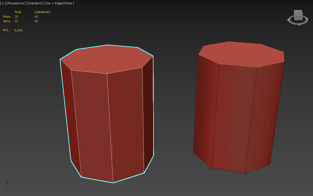
There is a difference between smooth shading and smoothing by adding more geometry.
I'll try to explain it as simply as possible, without getting too technical.
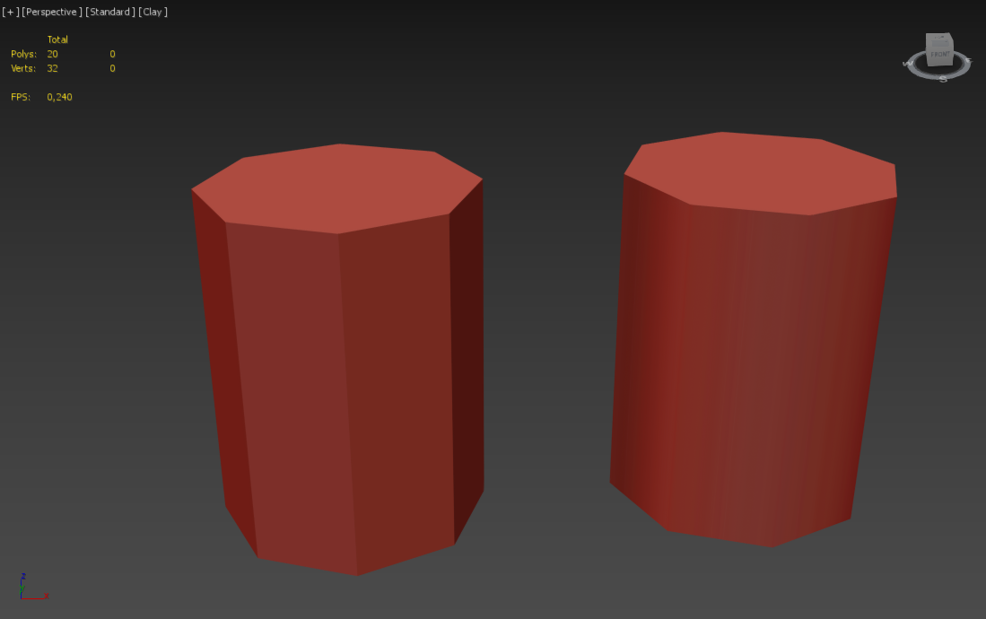
We have two Cylinders here:
At a first glance it is obvious that the one on the right looks much smoother than the one on the left, yet they have the exact same amount of vertices and polygons in 3ds max.
The difference between the two is, that the one on the right uses so called smoothing groups to render the faces/polygons going around the cylinder smoothly and not as facets. Smoothing Groups are a relatively Easy way to change the vertex normals on a 3d model, simply by defining groups of polygons that should shade smoothly.
A 3d editing program like gmax or 3ds max can store multiple of these vertex normals per vertex, this is really cool as it means you can easily edit the models as you see fit and still get the perfect shading you want. When it comes to model formats for games, like the md3 and glm format Jedi Academy - things get a little less comfortable.
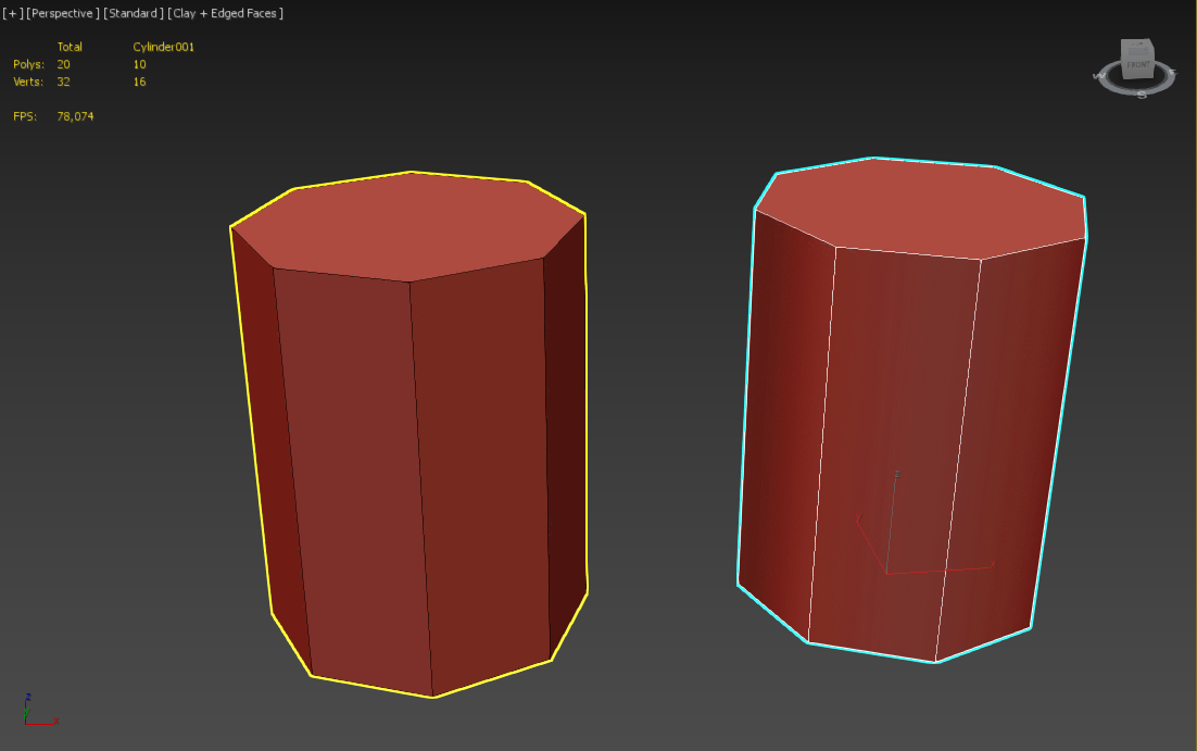
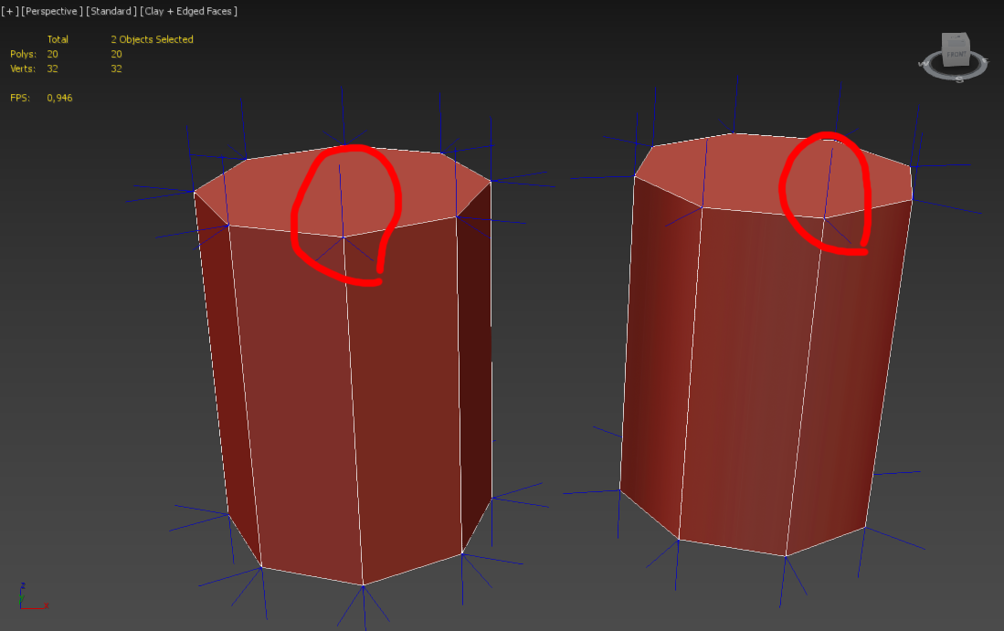
Both formats can only store a single vertex normal per vertex. Let's take a look at these vertex normals:
Each Line represents a vertex normal, as you can see - we have 2 lines per vertex on the right cylinder and 3 lines on each vert on the left cylinder.
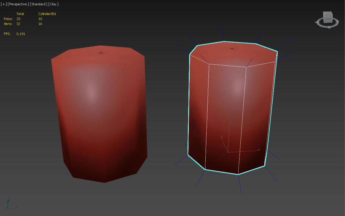
When you export these models to md3, the exporter splits the vertices once per vertex normal, so the vertex count of the model on the right DOUBLES and the vertex count of the model on the left TRIPLES after export.If we wanted the model to export without increasing the vertex count - we would need to do something like this:
While this gives us only one vertex normal per vertex, it comes at a horrible price - our cylinder now looks like a blob and no longer resembles what we want to have at all.
This is why you are getting so many additional vertices - your model looks like a disco ball, no edges are smoothed and so everything gets split up on export.
if you want to retain this look and still have the model usable ingame - you will need to seperate it into multiple submeshes.
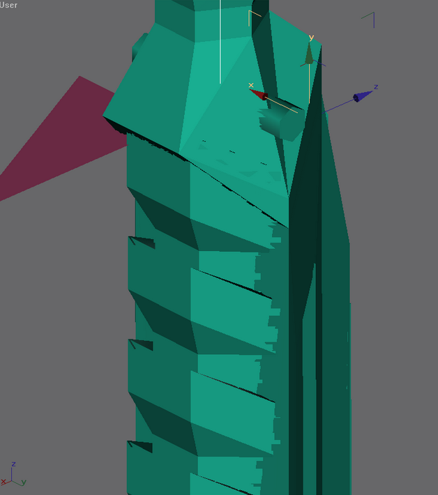
It is worth noting that the same applies to UV coordinates. MD3 and GLM Models can only store one set of texture coordinates per vertex while gmax and other 3d modeling programs can store way, way more than that. So you will also get multiplied vertices on uv seams, as a UV Seam is nothing but a vertex with mroe than one set of texture coordinates. As you can see here:
Hope this helps you to understand the concept
ooeJack likes this -
Hey,
There are two factors that increase Vertex count when exporting models for the game:
1. Non-smoothed/hard edges
2. UV Seams
Both cause the exporters to duplicate the vertices at those locations.
now onto Solutions:
1. Try tweaking the smoothing groups on your model to reduce the amount of hard edges
2. If you have not finalized your textures yet, try editing the UV Layout to reduce the number of seams (usually displayed as green edges in 3ds max and gmax too iirc)
3. Split the model into multiple sub-meshes that stay under 1000 verts each, this is usually the go-to solution but should be a last resort if you absolutely can not get below the threshhold on your mesh by following Solution 1 and 2
Let me know if you have further questions
Converting jk2 bones to jk3 bones
in Modding Assistance
Posted
@eduxdbossss2 Sorry, but that is something to ask the local blender Community, I work with a different Software (3ds max).
But generally a traceback hints at a mishandled exception in the exporter code. Try to provide more details and the full error message.