


Creating Curved (Corner) Cylinders
Szico VII
- Title: Creating Corner Cylinders
- Subject: How to create bends in pipes, t-junctions and corner pipes
- Written by: Szico VII
- Tutorial written for: GTK Radiant 1.4.0
- Similar concept work like in: N/A
- Difficulty level: 3/10
- Expected time to complete for first attempt: 5 mins
- Prerequisites: Ability to construct cylinders and use the grid
Creating Curved (Corner) Pipes
In order to create a ''curved'' pipe, which is basically a corner junction for two other pipes, you'll need to know a little bit about radiant and be able to effectively use the grid-snapping. However, this isn't too hard, and after a while you should be able to do it easily. So let's get started!
Firstly, make sure the ''Snap to grid'' option is turned on. You can do this by going to the ''Grid'' menu at the top, and then selecting ''Snap to grid.'' This (when turned on) will have a small tick next to it. This is important, as the curved patch involves editing vertices, which will deform the patch if a point is even one unit out of place. Therefore it is best to work to a large grid-size, and then resize the patch afterward. So set your grid-size to 256. (Again, under the grid menu.)
Now, you'll want to create a cubed box, with all it's dimensions the same. With the box selected, hit the ''Q'' key to bring up the measurements, and be sure each side is the same width (swap between views in radiant by pressing Shift+ Tab) Obviously, you can also easily tell by looking at the grid units in radiant, but when working with smaller grid sizes, this is a good check.
Now, select the cube, and go to the ''Curve'' menu, then select ''Cylinder.'' This will turn your cube into a cylinder. Rotate if necessary, until the side of the cylinder (i.e not the top circular bit) is in alignment with the original cube, as shown below:
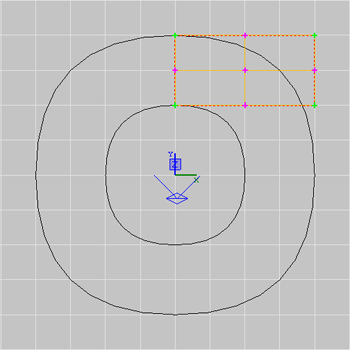
Now we need to start editing the vertices, so make sure the cylinder is selected and hit the ''V'' key. 9 Points (vertices) should show up on the 2D view, as shown below.
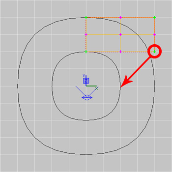
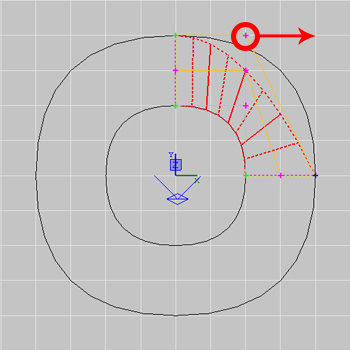
Ok, now we need to move these vertices around in order to create the curved pipe. Start by clicking the middle-right point (vertex), and dragging it up to the top-right vertex, so both the middle-right and top-right are now in the same place, as shown below. Note that you may need to change the gridsize down to 128 in order to align both properly.
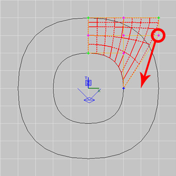
Note how I've decreased the grid-size (in the second picture, to 128, in order to put the point in the right place.) Next we need to move the bottom-right vertex, up to the middle-right point (which we had previously moved to the top.) The images below illustrate how it should be done.
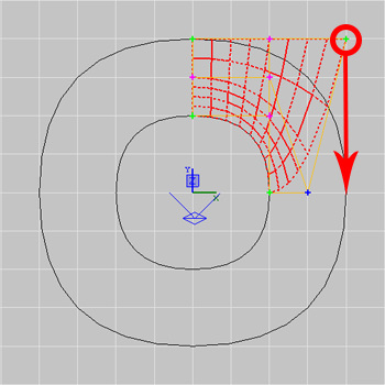
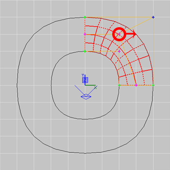
Now we need to move the middle-bottom vertex to the middle-right point. Just follow the diagrams below if you're unsure.
Nearly there! Okay, now take the bottom-left vertex and move it to the bottom-right point, as shown below:
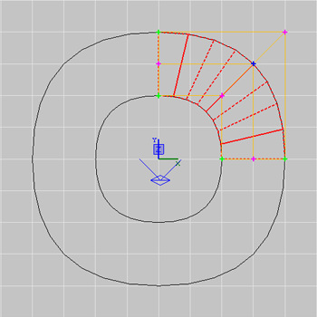
You'll notice it doesn't look quite right as it is, but don't worry, there is still one more vertex to move. Click the middle-left vertex and move it to the bottom-left point:
And there you go, a curved (corner) pipe. Feel free to resize it if need-be, and remember, when changing patch vertices, always try to stick to the grid, or you'll end up with some nasty results where things don't quite line up properly Feel free to texture your pipe now - hit ''V'' again to come out of vertex-editing mode, then select the pipe, choose a texture.
Creating T-Junction Pipes
Firstly, you'll need to create three identical cylinders with equal width, height and length. Place them as shown below:
The gap between the three cylinders should be the same size as the cylinders i.e if you made a fourth cylinder it would fit into the gap perfectly.
Okay, again press ''V'' to go into Vertex-Editing mode. Again put your grid-size down to 128, from 256 (or the one below whichever scale you are currently working at) so that you can place the points correctly. Firstly, select the lower cylinder (which is not in line with the other two.) and select the Top-Middle vertex. Drag it up to the centre point of the gap above, as shown below.
Now you need to do the same thing with the other two cylinders, with the left hand one, drag the middle-right point to the centre of the gap, and with the right hand one, drag the middle left point to the centre of the gap, as shown below.
Finally, you should take the top-right point of the left hand cylinder, and the top-left point of the right hand cylinder, and drag each vertex (separately though, not at the same time, or it won't work.) Into the top-middle point of the gap, as illustrated below.
Texturing this junction effectively can be a bit of a pain in the arse, so have a few experiments and see which things fit best for the pipes. You CAN resize this construction, however you need to resize each cylinder separately, or it will go wrong. Don't try selecting all three cylinders and re-sizing. Rotation is fine and you can use it for this construction as you would a set of brushes.
Creating Hollow Pipes
So now you know how to create curving cylinders and T-junctions. But what if you want a hollow pipe? One that a player can walk through or one which has an opening to look into? To do this, the edge (or wall) of the pipe needs to be given depth, which a single patch on its own does not have, as it only essentially has one face, unlike a brush. In order to accomplish this, we must use several patches - one for the outer surface of the pipe, one for the inner surface of the pipe, and one to cap the end of the pipe, joining the inner and outer surfaces together.
So here is how you go about it. For the purposes of this tutorial and for learning, follow the exact design of the pipe shown here - but remember you can of course change the dimensions, thickness and size of any of the components once you are familiar with the construction process.
Firstly, create a brush that is 512(W)x512(D)x256(H) units in radiant. You can press the Q key to have radiant show you the units. I'm am using Grid size 64 for this tutorial - because remember, the vertex movements must be precise and having them even a single unit out of place will cause misalignment. Then make sure you are looking at the brush from the top-down view in radiant (XY view)
Now select your brush, and go to the menu:
CURVE -------> CYLINDER.
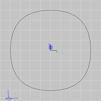
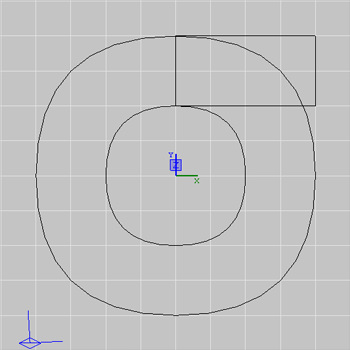
This will convert your brush into a cylindrical patch mesh as shown below
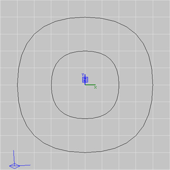
Now create a second brush in the center of the cylinder with dimensions 256x256x256. Repeat the process to convert this into a cylindrical patch mesh, as shown below:
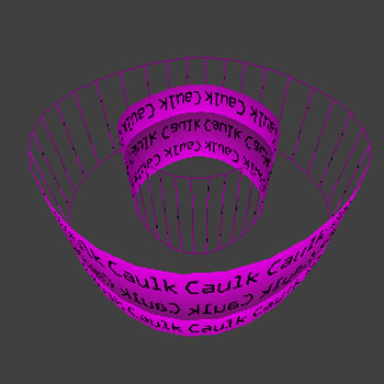
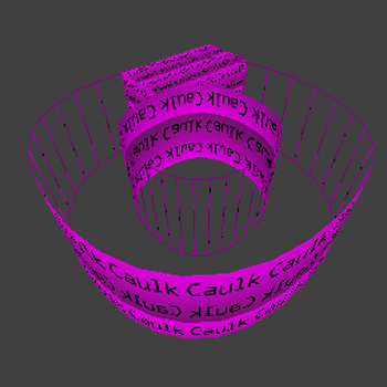
Once this mesh has been created, you need to invert its surface so the textured side is facing inwards. With the smaller cylinder selected, you can do this with the keyboard shortcut Ctrl+I. Alternatively, you can go Curve----->Matrix------->Invert.
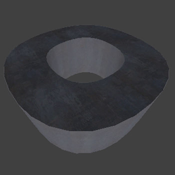
Your construction should now look like this:
Now we have both the inner and outer surface of our hollow pipe. The next job is to cap the end off so it will appear to the player in-game that the pipe has true thickness. This is done using a different type of patch, the 'simple patch mesh.'
Capping the Pipe
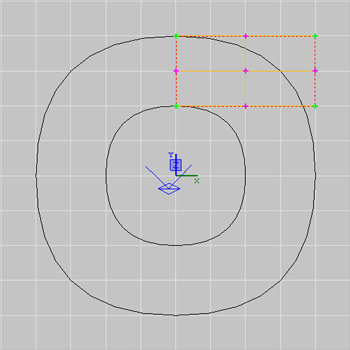
Create a third brush (of any depth, it does not matter) which spans the distance between the outer and inner cylinders vertically, and the far right edge of the outer cylinder horizontally, as depicted below:
Now, with this brush selected, turn it into a simple patch mesh as follows:
Curve------>Simple Patch Mesh. (Alternatively use the shortcut Shift+P)
This will bring up a small menu labelled 'Patch Density.' You will want to leave the values as they are, at 3 for width and 3 for height. (This determines the number of vertices used to control the patch. You should always use the minimum number possible for the construction required, for simplicity. Click 'OK' and you should now have a simple patch mesh that looks like this:
Press the 'V' key to enter vertex editing mode. Your patch should have 9 vertices.
Now we must move these vertices, as in the previous sections, to align this patch between the inner and outer cylinders around the top right quarter of the shape.
Firstly, select the Bottom-Right vertex and move it 2 grid boxes (128 units on a 64-size grid) below the Bottom-Middle vertex, as shown below.
Next, select the Middle-Right vertex and move it 1 grid box to the right of the vertex you previously moved:
Then, select the Top-Right vertex, and move it 1 grid box to the right of the previous vertex you moved.
Next, select the Top-Middle vertex, and move it to where the Top-Right vertex originally was (2 grid boxes to the right):
Finally, move the Middle-Center vertex to where the Middle-Right vertex originally was (2 grid boxes to the right):
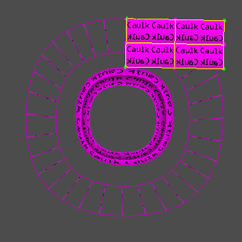
Your construction should now appear as shown below:
Now, the only thing left to do is to duplicate your patch (Ctrl+C) and paste it (Ctrl+V.) Then rotate the new patch mesh 90 degrees using the z-axis rotate tool, and repeat the copy and rotate twice more until the entire edge has been capped. Then all you have to do is apply your textures (Shift+S). Use the 'Cap' fit option on the simple patch meshes and the 'natural' fit option on the cylinders for the best effect!
NB: Remember if resizing you must re-size each patch individually to avoid deforming the other patches. An alternative would be to merge your 4 simple patch meshes together using Plugins------>Bobtoolz------>Merge Patches. It'll only let you merge 2 at once though, so you'll have to merge 2 quarters together on each side, and then merge the 2 newly created halves together afterward for one single , convenient patch.


Recommended Comments
Create an account or sign in to comment
You need to be a member in order to leave a comment
Create an account
Sign up for a new account in our community. It's easy!
Register a new accountSign in
Already have an account? Sign in here.
Sign In Now